
Drone with ring assembly

a technology of drones and rings, applied in the field of drones with rings, can solve the problems of limited use of unmanned aerial vehicles such as quadrotors, limited use of unmanned aerial vehicles, and limited use by users, and achieve the effect of ensuring high performance and wide view

Active Publication Date: 2018-10-16
GONZALEZ OSWALDO
View PDF13 Cites 13 Cited by
  • Summary
  • Abstract
  • Description
  • Claims
  • Application Information

AI Technical Summary

Benefits of technology

The present unmanned aerial vehicle (UAV) is a self-propelled precision-guided munition system with advanced tactical information in real-time through electro-optic and lasers. It can automatically navigate routes, access locations, or attack objectives preset or preplanned, guided by GPS. It can hold up in the air, come back to land, or adjust its speed and height. It can target and surveillance in crowded civil events with high resolution cameras. It can perform at any environment, with high performance on high or low temperatures.

Problems solved by technology

Traditionally usage of unmanned aerial vehicle UAV's such as quadrotors, by users is limited to entertainment as toys or as hobbyist collector items.
Further, the military personnel are also utilizing unmanned aerial vehicles or drones in situations where manned aerial vehicles are considered too risky or difficult.
However, the existing UAVs function in specified environmental conditions because of various limitations such as extreme temperature, weather conditions, obstructions etc.
Further the existing UAVs have technical limitations as well.
For instance, most UAVs expose the propellers to the external side, allowing for environmental factors and obstacles to harm the UAV.
Further the existing UAVs are not capable enough to store items and then deploy those items to the targeted area.
This brings with it a delay in the execution of the actions that must be taken instantly.

Method used


Image

  • Drone with ring assembly
  • Drone with ring assembly
  • Drone with ring assembly

Examples


Embodiment Construction

[0026]The present disclosure is best understood with reference to the detailed figures and description set forth herein. Various embodiments have been discussed with reference to the figures. However, those skilled in the art will readily appreciate that the detailed descriptions provided herein with respect to the figures are merely for explanatory purposes, as the methods and systems may extend beyond the described embodiments. For instance, the teachings presented and the needs of a particular application may yield multiple alternative and suitable approaches to implement the functionality of any detail described herein. Therefore, any approach may extend beyond certain implementation choices in the following embodiments.

[0027]References to “one embodiment”, “at least one embodiment”, “an embodiment”, “one example”, “an example”, “for example”, and so on indicate that the embodiment(s) or example(s) may include a particular feature, structure, characteristic, property, element, o...


PUM


Abstract

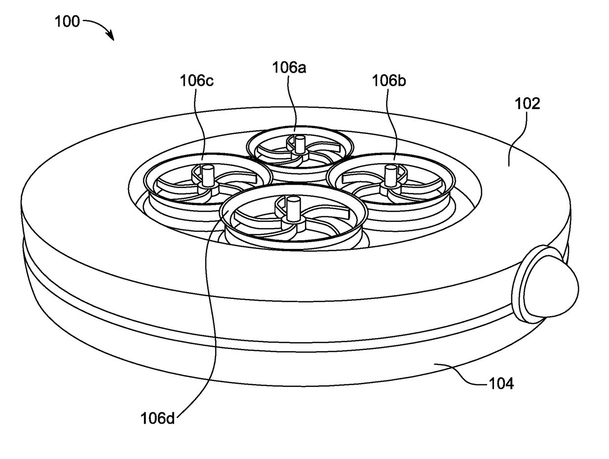
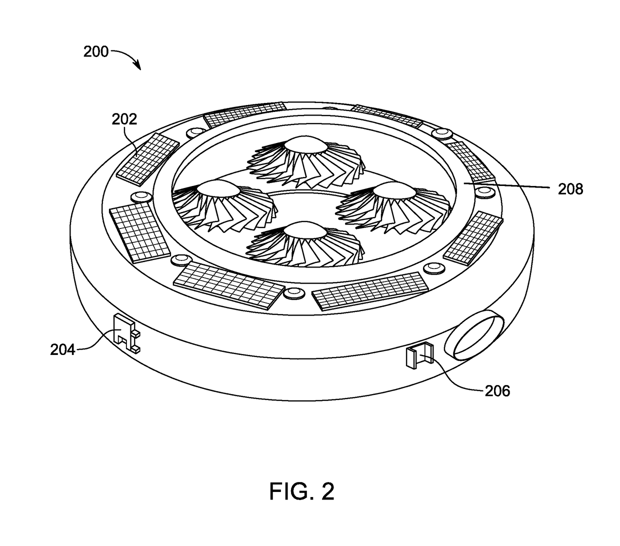
Disclosed is an unmanned aerial vehicle (UAV) with a pre-defined shape to deploy one or more items. The unmanned aerial vehicle (UAV) includes an upper housing, a lower housing, and a power unit. The upper housing includes plurality of rotors to lift and propel the unmanned aerial vehicle (UAV). Further the unmanned aerial vehicle (UAV) includes various electronic components such as plurality of electronic cards, a processing unit, a Global Positioning System (GPS), a communication unit, an electronic gyroscope, a barometer, engines and flight control system, video camera, a forward looking infrared (FLIR) device, a microphone, and a laser telemeter / designator / range finder. The power unit powers the aforementioned electronic components. The lower housing includes plurality of storage units to stores one or more items. The lower housing is removably attached with the upper housing in a way to deploy the items at a predetermined location through plurality of openings.

Description

TECHNICAL FIELD[0001]The present invention is generally related to an unmanned aerial vehicle (UAV), particularly to a recoverable unmanned aerial vehicle (UAV) with a pre-defined shape to deploy one or more items.BACKGROUND[0002]Traditionally usage of unmanned aerial vehicle UAV's such as quadrotors, by users is limited to entertainment as toys or as hobbyist collector items. Recently, however, UAV's have been used for personal photography and videography and many other commercial applications. Further, the military personnel are also utilizing unmanned aerial vehicles or drones in situations where manned aerial vehicles are considered too risky or difficult. The UAVs provide military personnel with a round the clock monitoring of the target area.[0003]However, the existing UAVs function in specified environmental conditions because of various limitations such as extreme temperature, weather conditions, obstructions etc. Further the existing UAVs have technical limitations as well....

Claims


Application Information

Patent Timeline
IPC IPC(8): B64C39/02B64D47/08B64D7/00
CPCB64C39/024B64D47/08B64D7/00B64C2201/128B64C2201/121B64C2201/127B64C2201/027B64C2201/108B64U2101/30B64U50/14B64U80/30B64U20/20B64U20/83B64U2101/31B64U30/294B64U50/19B64U30/26B64U10/14B64U20/40B64U2101/18B64U2101/60B64U50/31B64U2101/17B64U80/70B64U20/87B64U2101/19B64U10/13B64U30/20B64U2101/15
Inventor GONZALEZ, OSWALDO
Owner GONZALEZ OSWALDO
Learn More