Control system and control method for a phase shifted full bidge charger

a control system and charger technology, applied in secondary cell servicing/maintenance, safety/protection circuits, transportation and packaging, etc., can solve the problems of system overshoot, individuality of each running mode cannot be satisfied, voltage and current control in a steady state cannot be controlled, etc., to achieve the effect of small overshoot, fast response time and optimal stable

Inactive Publication Date: 2018-10-09
CRRC QINGDAO SIFANG ROLLING STOCK RES INST
View PDF7 Cites 0 Cited by
  • Summary
  • Abstract
  • Description
  • Claims
  • Application Information

AI Technical Summary

Benefits of technology

[0055](2) The controller of the present application further includes a smooth switchover control unit. When the charger is switched between different operation modes or running states, the smooth switchover of the control parameters (i.e., the control methods) between the control units can be achieved, with a small amount of overshoot and fast response time. Thus, good steady performance and dynamic performance are achieved.

Problems solved by technology

If three groups of the same proportional parameters and integral parameters are used, the individuality of each running mode cannot be satisfied, and the technical requirements of controlling both the voltage and the current in a steady state cannot be fulfilled.
If three groups of different proportional parameters and integral parameters are used, at the moment of switchover between two control strategies, the proportional parameters and the integral parameters are to be switched quickly, thus leading to overshoot in voltage and current when the system is dynamically adjusted, or even damage in extreme situations.
At present, there is no one control method that can ensure smooth switchover of a PSFB charger for a train between different running modes, and also stable operation of the PSFB charger at the moment of and after the switchover between different running modes.

Method used


Image

  • Control system and control method for a phase shifted full bidge charger
  • Control system and control method for a phase shifted full bidge charger
  • Control system and control method for a phase shifted full bidge charger

Examples


Embodiment Construction

[0062]The specific implementations of the present application will be further described below in detail with reference to the accompanying drawings.

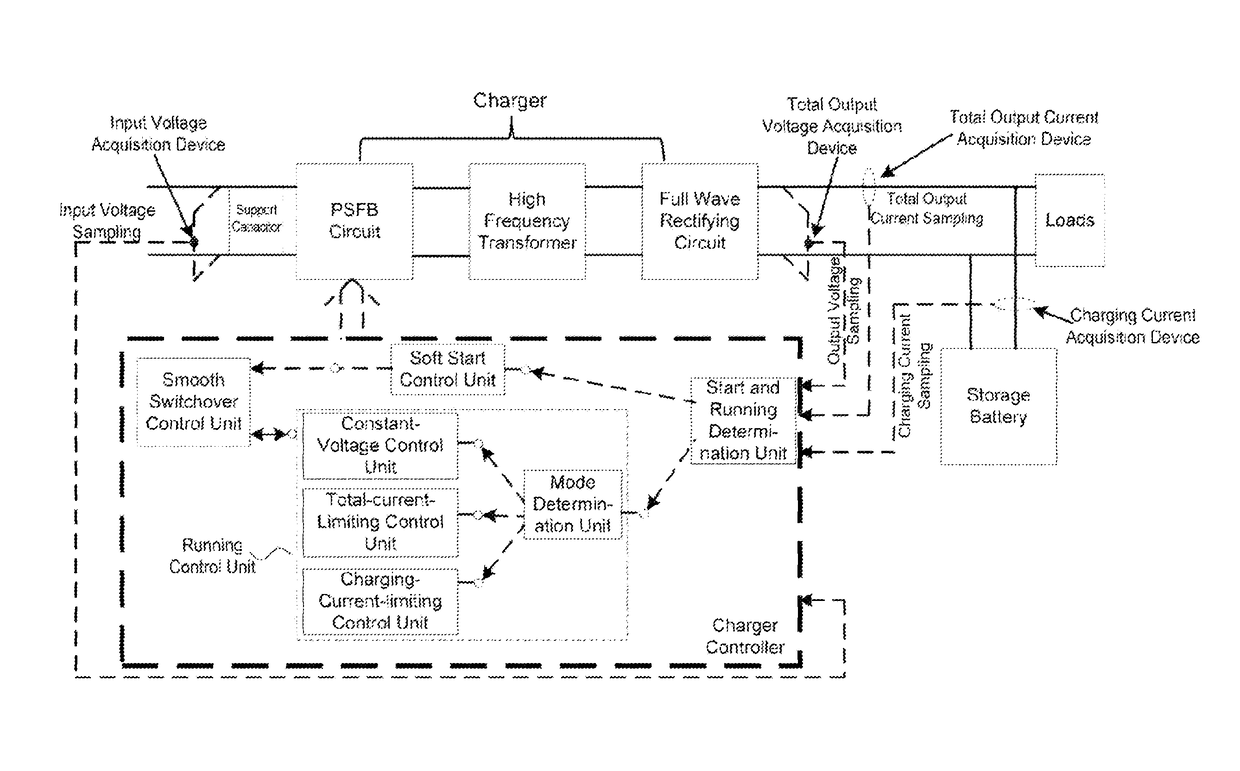
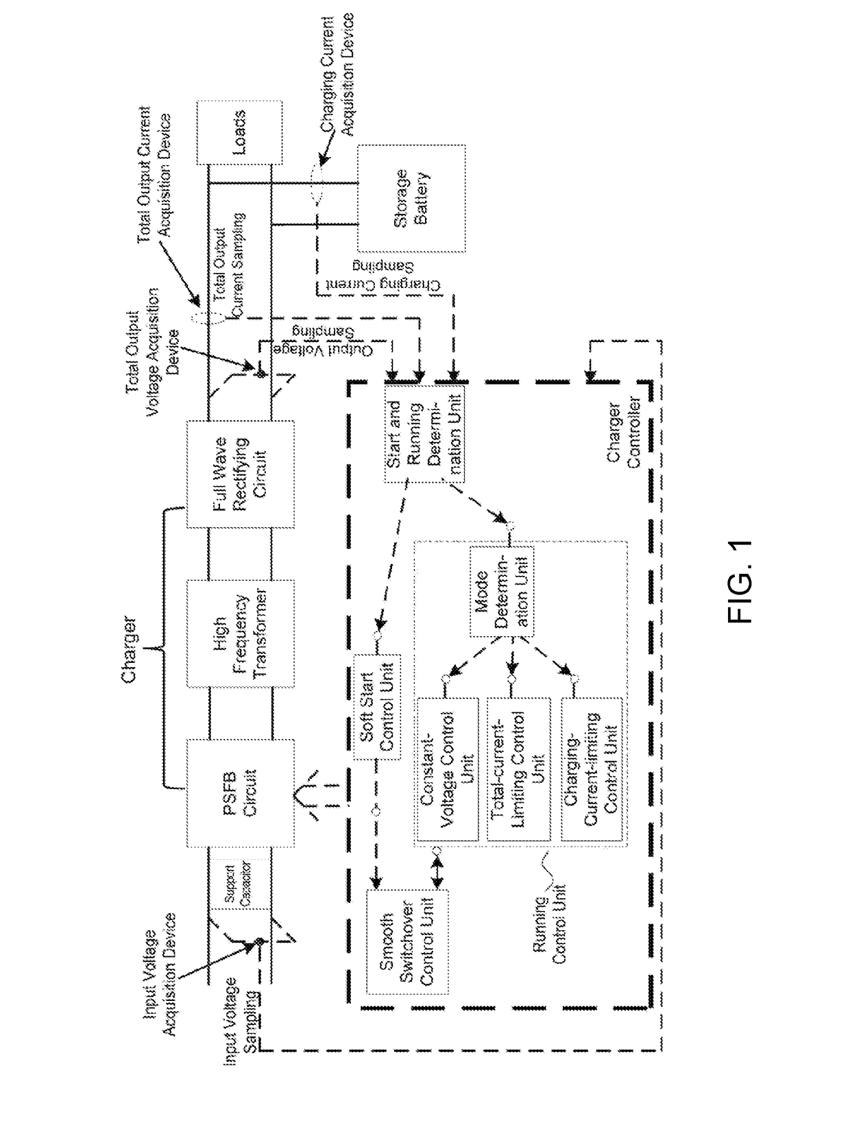
[0063]As shown in FIG. 1, the structure of the PSFB charger comprises a PSFB circuit, a high frequency transformer and a rectifying circuit, which are connected successively, wherein, an output terminal of the rectifying circuit is connected to a storage battery and loads, respectively, to charge the storage battery and drive the loads to run.

[0064]It should be noted that the chargers described in this implementation are all PSFB chargers.

[0065]The operating principle of a PSFB charger is as follows:

[0066]1. In the PSFB circuit for the charger, a voltage conversion is realized by a PSFB zero-voltage PWM (Pulse Width Modulation) converter, and a high DC voltage is input by the PSFB circuit to output a low DC voltage which is stable and adjustable.

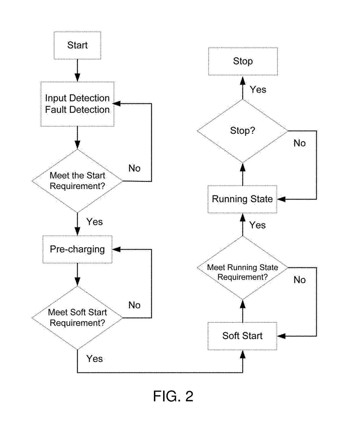
[0067]2. A normal operating process of the charger is as follows: firstly, an input DC voltag...


PUM

PropertyMeasurementUnit
voltageaaaaaaaaaa
current Ioutaaaaaaaaaa
voltageaaaaaaaaaa

Abstract

A control system and control method for a phase shifted full bridge charger, wherein, the control system comprising a sampling system and a charger controller, the charger controller comprises a start and running determination unit, a soft start control unit, a running control unit and a smooth switchover control unit; the running control unit comprises a mode determination unit, a constant-voltage control unit, a total-current-limiting control unit and a charging-current-limiting control unit. During the operation of the charger, after soft start ends, switching occurs between a constant-voltage running state, a total-current-current-limiting running state and a charging-current-limiting running state according to differences in conditions, and the smooth switchover control unit enables the controller to switch between the operation states according to differences charger operation states to realize smooth switching within the charger control method and have high steady-state performance and dynamic performance.

Description

CROSS REFFERENCE TO RELATED APPLICATION[0001]This application is a national phase application of international application No. PCT / CN2016 / 109409 filed on Dec. 12, 2016, which in turn claims the priority benefits of Chinese application No. 201610688741.2, filed Aug. 17, 2016. The contents of these prior applications are hereby incorporated by reference in their entirety.TECHNICAL FIELD[0002]The present invention belongs to the technical field of control to chargers, and relates to a control system and control method for a phase shifted full bridge charger having multiple running modes.BACKGROUND OF THE INVENTION[0003]Train chargers are used to supply power to all the DC loads in the train and charge storage batteries. According to different operating conditions of a train, a charger has multiple running modes, specifically including a constant-voltage mode, a charging-current-limiting mode and a total-current-limiting mode. To ensure the stable operation of a charger, each running mo...

Claims


Application Information

Patent Timeline
Patent Type & Authority Patents(United States)
IPC IPC(8): H02J7/00H01M10/44H02M1/36
CPCH02J7/007H01M10/44H02M1/36H02J2007/0039H02J7/0029H02J7/0047Y02E60/10H02J7/00304H02J7/02H02J7/00
Inventor LIN, XIANQIZHANG, LIJUNZHAO, XUQIANGSUN, SHIYING
Owner CRRC QINGDAO SIFANG ROLLING STOCK RES INST
Why Eureka
Try Eureka