
Organic light-emitting display apparatus and method of manufacturing the same

a technology of light-emitting display apparatus and organic materials, which is applied in the direction of vacuum evaporation coating, solid-state devices, coatings, etc., can solve the problem that the mask may inappropriately contact the substrate, and achieve the effect of simplifying the overall manufacturing process and reducing manufacturing costs

Active Publication Date: 2018-10-02
SAMSUNG DISPLAY CO LTD
View PDF17 Cites 1 Cited by
  • Summary
  • Abstract
  • Description
  • Claims
  • Application Information

AI Technical Summary

Benefits of technology

The invention relates to a method of manufacturing organic light-emitting display apparatuses using a lift-off process. This method eliminates the need for a fine metal mask, which can cause issues during deposition. As a result, manufacturing costs are reduced and the manufacturing process is simplified.

Problems solved by technology

Applicants discovered that when a deposition process is performed in a state where a substrate and a mask are in close contact, the mask may inappropriately contact the substrate.

Method used


Image

  • Organic light-emitting display apparatus and method of manufacturing the same
  • Organic light-emitting display apparatus and method of manufacturing the same
  • Organic light-emitting display apparatus and method of manufacturing the same

Examples


first embodiment

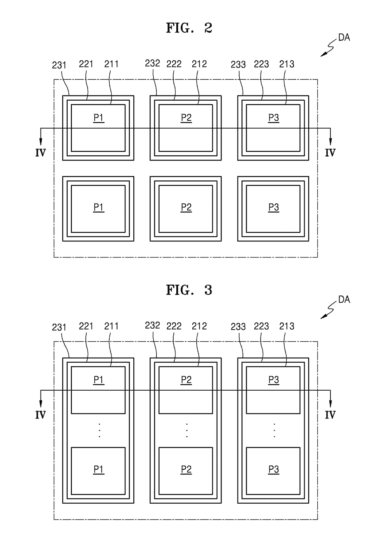
[0055]FIG. 2 is a schematic plan view of a part of a display area of the organic light-emitting display apparatus of FIG. 1. FIG. 3 is a schematic plan view of another embodiment of a part of a display area of the organic light-emitting display apparatus of FIG. 1. FIG. 4 is a schematic cross-sectional view of the organic light-emitting display apparatus taken along sectional line IV-IV of FIGS. 2 and 3.

[0056]Referring to FIGS. 2 through 4, the display area DA includes pixels P1, P2, and P3 that emit light of different colors. For descriptive convenience, the pixels P1, P2, and P3, which may emit light of different colors, are respectively referred to as a first pixel, a second pixel, and a third pixel.

[0057]In an exemplary embodiment, the first pixel P1 may emit red light, the second pixel P2 may emit green light, and the third pixel P3 may emit blue light. Although three pixels, the first through third pixels P1, P2, and P3, are located in the display area DA in the illustrated em...

second embodiment

[0129]FIG. 7 is a schematic cross-sectional view of an organic light-emitting display apparatus constructed according to the principles of the invention. FIGS. 8A and 8B are schematic cross-sectional views of the organic light-emitting display apparatus of FIG. 7 illustrating a part of an exemplary method of manufacturing the organic light-emitting display apparatus.

[0130]Referring to FIG. 7, the organic light-emitting display apparatus 2 according to the second embodiment is substantially the same as the organic light-emitting display apparatus 1 of FIG. 4 except for anti-decapping particles 2720, and thus the following description will focus on the differences.

[0131]The first through third pixels P1, P2, and P3 include the pixel circuits PC and the first through third OLEDs 201, 202, and 203 electrically connected to the pixel circuits PC, and the first through third pixel electrodes 211, 212, and 213, the first through third intermediate layers 221, 222, and 223, and the first th...


PUM

PropertyMeasurementUnit
DAaaaaaaaaaa
thicknessaaaaaaaaaa
thicknessaaaaaaaaaa

Abstract

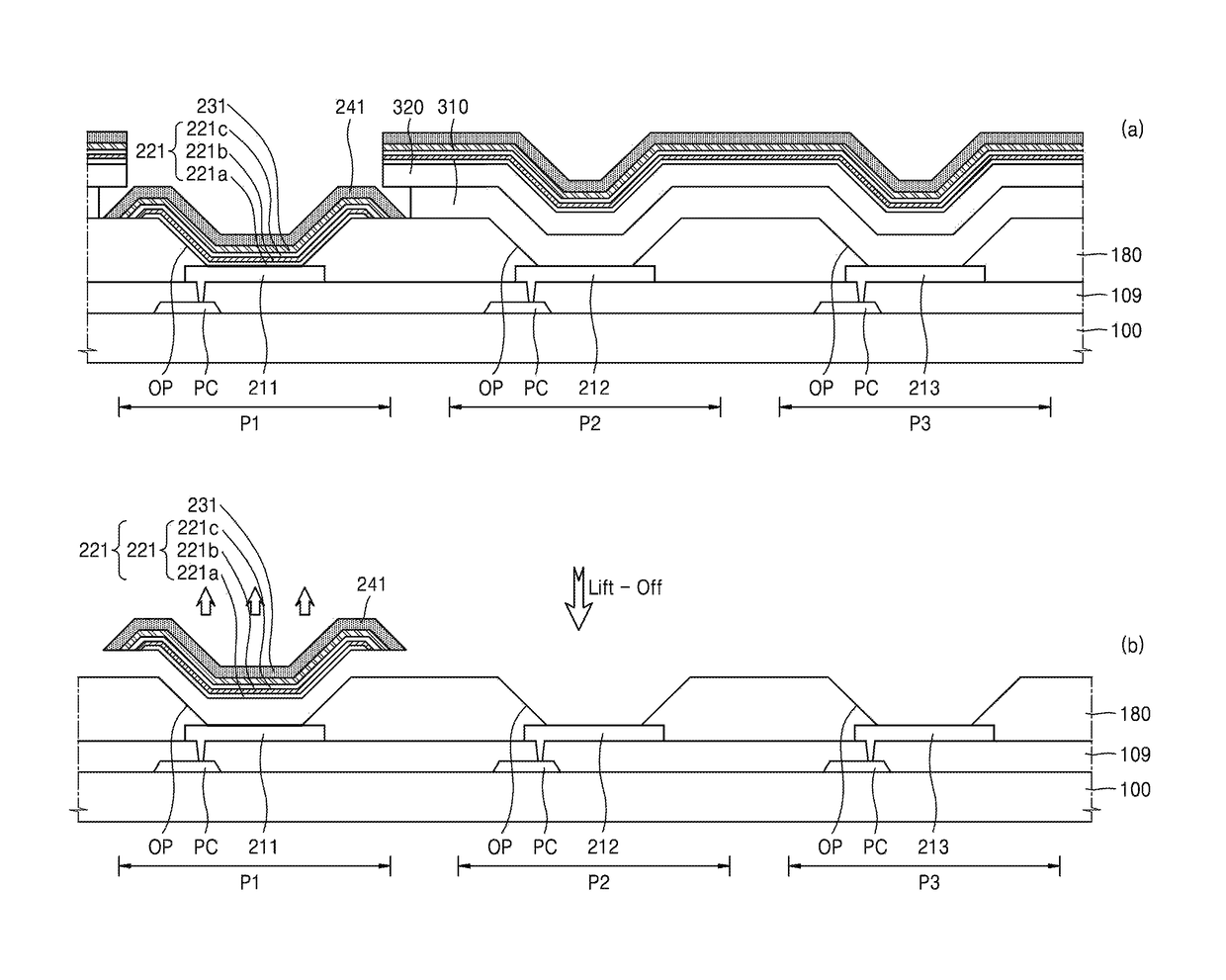
A method of manufacturing an organic light-emitting display apparatus includes the step of forming a first pixel electrode and a second pixel electrode on a substrate, forming a pixel-defining film on the first pixel electrode and the second pixel electrode, the pixel-defining film having an opening through which each of the first pixel electrode and the second pixel electrode is exposed, forming a first masking pattern on the pixel-defining film having a first opening portion through which the first pixel electrode is exposed, sequentially forming a first intermediate layer including a first emission layer, a first counter electrode, a first protective layer, and a first anti-decapping layer on the first pixel electrode and the first masking pattern, and removing the first masking pattern along with the first intermediate layer, the first counter electrode, the first protective layer, and the first anti-decapping layer disposed on the first masking pattern.

Description

CROSS-REFERENCE TO RELATED APPLICATION[0001]This application claims priority from and the benefit of Korean Patent Application No. 10-2017-0030311, filed on Mar. 10, 2017, which is hereby incorporated by reference for all purposes as if fully set forth herein.BACKGROUNDField[0002]The invention relates generally to organic light-emitting display apparatuses, and more particularly, to organic light-emitting display apparatuses and methods of manufacturing organic light-emitting apparatuses that may be produced at reduced manufacturing costs and can simplify the overall manufacturing process.Discussion of the Background[0003]Organic light-emitting display apparatuses are widely used as next generation display apparatuses because of their wide viewing angle, short response time, and low power consumption as well as thin and light design.[0004]In an organic light-emitting display apparatus capable of displaying a full color image, light having different colors is emitted from pixel regio...

Claims


Application Information

Patent Timeline
Patent Type & Authority Patents(United States)
IPC IPC(8): H01L51/52H01L27/32H10K99/00
CPCH01L27/3209H01L51/5203C23C14/042C23C14/24H10K59/122H10K50/844H10K71/00H10K71/12H10K59/12H10K71/221H10K59/131H10K59/1201H10K59/805H10K59/123H10K50/805H10K59/32
Inventor KWON, YOUNGGILCHOUNG, JIYOUNGLEE, SEULCHOI, JINBAEK
Owner SAMSUNG DISPLAY CO LTD
Learn More