
Massage device

a technology of massaging device and massage head, which is applied in the direction of roller massage, mechanical vibration separation, sport apparatus, etc., can solve the problems of affecting the massage effect, and causing disturbance noises with the frequency of vibrations in most cases

Active Publication Date: 2018-10-02
BLENK UDO +1
View PDF27 Cites 6 Cited by
  • Summary
  • Abstract
  • Description
  • Claims
  • Application Information

AI Technical Summary

Benefits of technology

The invention is a massaging device that performs soft and impact-free movements using end magnets. It reduces the overall length of the device while maintaining its effectiveness. The device also prevents noisy sounds caused by hitting the core on the ends of the cylinder element. The end magnets operate with almost no loss of energy, and the device has a long lifespan. The cylinder element is made of a metallic material with low permeability, which prevents whistle sounds and rattling noises. The device can use various magnetic materials, and the electronic control allows for uniform and non-harmonic vibrations. The inner wall of the cylinder element and the outer wall of the core can have a lubricious coating to reduce friction and energy consumption.

Problems solved by technology

In addition, disturbing noises with the frequency of the vibrations will in most cases be caused.
All this is disadvantageous for the application of the massaging device, as this is perceived as rather disturbing.
Consequently, the massage effect is rather low.
In the insofar known massaging device, details are however improvable, particularly with respect to the impact elements, which limit or dampen the movements of the core in the areas of motion reversal.
I.e. the used springs and / or foam materials or the like may, on one hand, “break down” at very high vibration amplitudes of the core, with the result that impacts and related noise are noticeable, both of which are uncomfortable.
In addition, particular foam materials used as impact elements wear over time and lose their cushioning effect, again with the consequence of increasingly noticeable impacts and audible noise.

Method used


Image

  • Massage device
  • Massage device
  • Massage device

Examples


Embodiment Construction

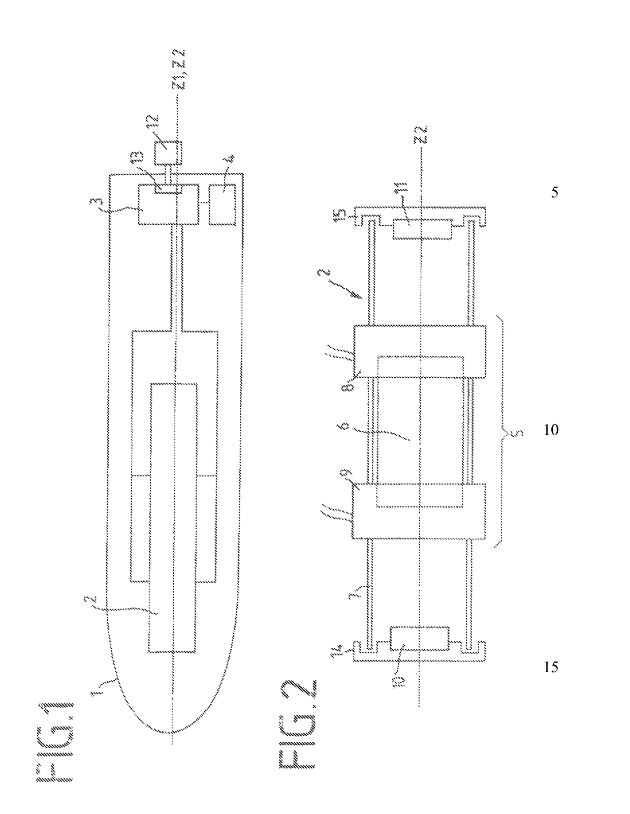
[0011]To solve this technical problem, the invention teaches that the impact elements are formed as end magnets, wherein the ends of the end magnets respectively facing the ends of the core have a magnetic polarity, which is identical to the polarity of the respectively facing ends of the core.

[0012]The direction of magnetization of both the core and the end magnets is parallel, in particular coaxial with respect to the (longitudinal) housing axis, so that the magnets have at each of their ends, as seen in the direction of the (longitudinal) housing axis, a north and a south pole each. The end magnets can be configured as permanent magnets as well as electric magnets.

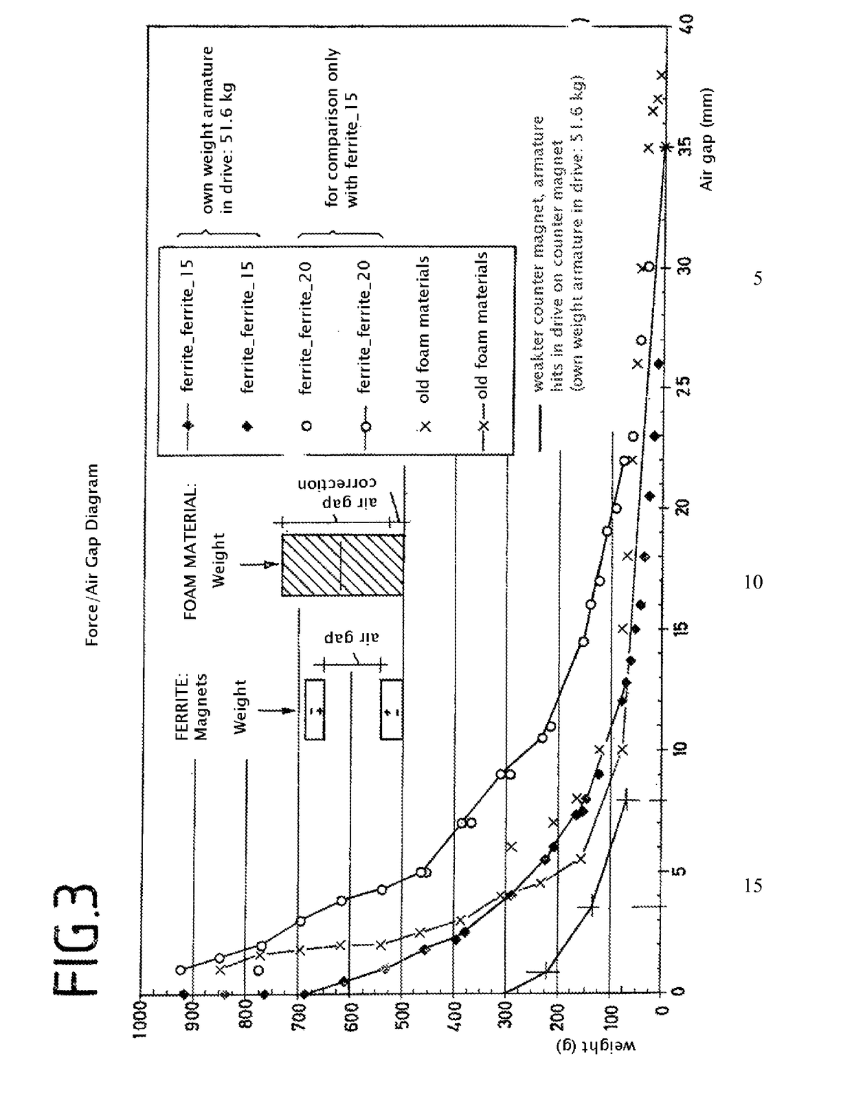
[0013]By the invention, it is achieved, on one hand, that the massaging device performs particularly soft and in particular impact-free reciprocating movements, because the end magnets very softly and progressively dampen any kinetic excess energy of the core in the area of the motion reversal points. Further, disturbin...


PUM


Abstract

The massaging device includes electromechanical means, for generating mechanical vibrations, in a housing, electronic means for controlling the electromechanical means, and a power source connected to the electromechanical and electronic means. The electromechanical means includes a cylinder element, in which a core is guided in parallel to a cylinder element axis (Z2), in particular, coaxial with respect to the cylinder element axis (Z2), at least one coil element, the coil axis (Z3) of which is arranged coaxially with respect to the cylinder element, and which encloses the cylinder element, and one impact element arranged at each end of the cylinder element and in the interior thereof, characterized in that the impact elements are formed as end magnets, wherein the ends of the end magnets respectively facing the ends of the core have a magnetic polarity which is identical to the polarity of the respectively facing ends of the core.

Description

FIELD OF THE INVENTION[0001]The invention relates to a massaging device, particularly for sexual stimulation, comprising electromechanical means for generating mechanical vibrations disposed in the housing, electronic means for controlling the means for generating mechanical vibrations disposed in the housing, and a power source, which is connected to the means for generating mechanical vibrations and to the electronic means, the means for generating mechanical vibrations including at least one coil element and at least one ferromagnetic core arranged parallelly or coaxially with respect to the coil element and displaceably guided parallelly to a cylinder axis of the housing. Furthermore, the invention relates to the use of such a massaging device for sexual stimulation.PRIOR ART AND BACKGROUND OF THE INVENTION[0002]Massaging devices for sexual stimulation are known in the art from the documents U.S. Pat. No. 3,991,751 and U.S. Pat. No. 4,377,692. These are mainly devices in a shape...

Claims


Application Information

Patent Timeline
Patent Type & Authority Patents(United States)
IPC IPC(8): A63B24/00A61H19/00A61H23/02B06B1/04A61H15/00A61H23/00
CPCA61H19/44A61H15/0085A61H23/0218B06B1/045A61H19/34A61H2023/002A61H9/0071A61H2201/0142A61H2201/0153A61H2201/0169A61H2201/5005
Inventor BLENK, UDOSTOEHR, STEFAN
Owner BLENK UDO
Learn More