
Rotor of a supercharging device

Inactive Publication Date: 2018-09-18
BOSCH MAHLE TURBO SYST GMBH & CO KG
View PDF22 Cites 0 Cited by
  • Summary
  • Abstract
  • Description
  • Claims
  • Application Information

AI Technical Summary

Benefits of technology

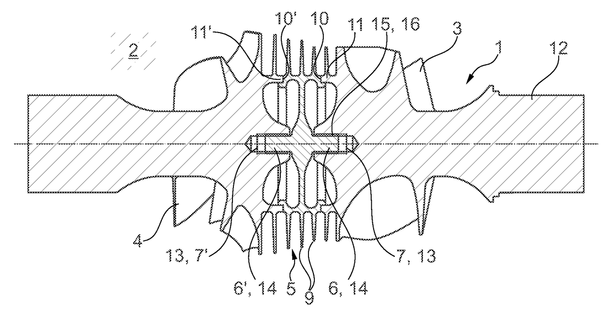
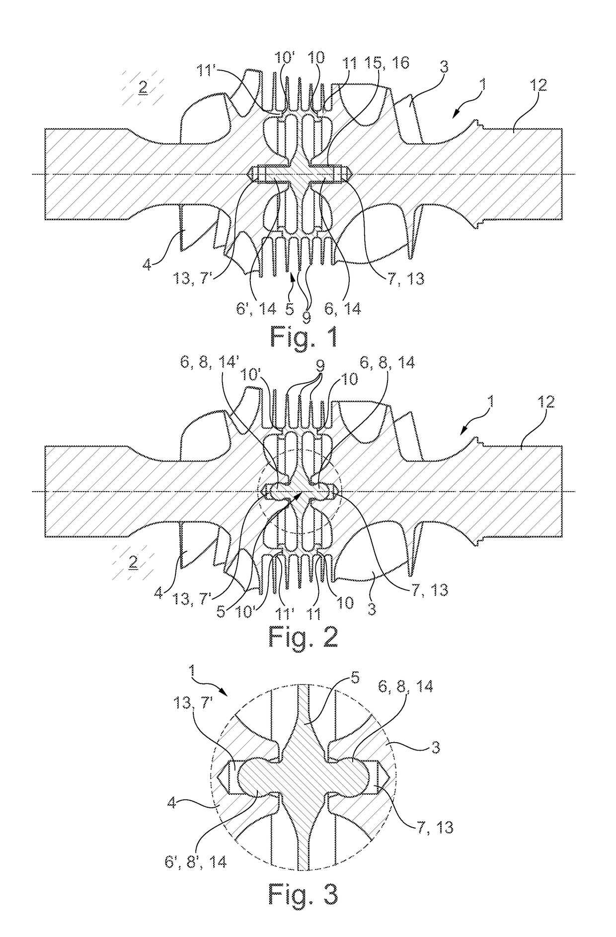
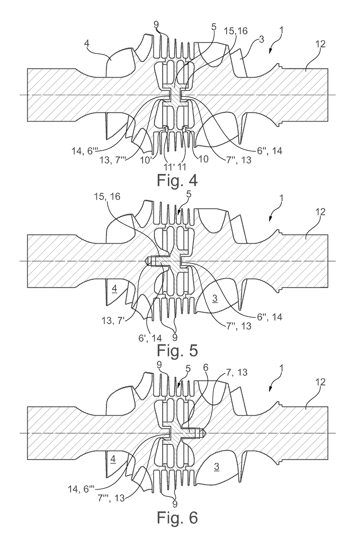
The technical effects of the invention are: a simplified assembly of rotor components with a durable and reliable connection, achieved through the use of sealing disc with central recesses and associated axial extensions that fasten the components to each other and provide centring and additional fixing during operation. The sealing disc can also be easily disconnected for maintenance purposes. Furthermore, the invention provides the option of a screw connection between the components, which further simplifies assembly and maintenance.

Problems solved by technology

In the case of thicker shafts or in the case of a compressor wheel arranged directly on the turbine wheel welding however is not possible or only to a limited extent.
Disadvantageous with such an embodiment however is that with a diminishing sub-pressure there is the risk of the turbine wheel detaching from the compressor wheel and thus the risk of the rotor breaking apart, which because of the high rotational speeds of the rotor often results in a total destruction of the supercharging device.

Method used


Image

  • Rotor of a supercharging device
  • Rotor of a supercharging device
  • Rotor of a supercharging device

Examples


Embodiment Construction

[0025]According to the FIGS. 1 to 4, a rotor 1 according to the invention of a supercharging device 2 which is merely shown in outline, which in particular can be designed as an exhaust gas turbocharger, comprises a compressor wheel 3 and a turbine wheel 4 connected thereto. The compressor wheel 3 and the turbine wheel 4 each have a holding contour 13 and the sealing disc 5 a counter-holding contour 14 formed complementarily thereto, or vice versa (see FIG. 4). With the embodiments shown in FIGS. 5 and 6, the sealing disc 5 comprises a central counter-holding contour 14 and located opposite a central holding contour 13 and the compressor wheel 3 and the turbine wheel 4 each comprise a holding contour 13 or a counter-holding contour 14 each formed complementarily thereto. All shown embodiments in this case have in common that the holding contour 13 and the counter-holding contour 14 engage in one another in the assembled state and in addition fasten the compressor wheel 3, the sealin...


PUM


Abstract

A rotor for a supercharging device may include a compressor wheel and a turbine wheel. A sealing disc may be arranged between the compressor wheel and the turbine wheel. The sealing disc may include a first side interfacing with the compressor wheel and a second side interfacing with the turbine wheel. The compressor wheel and the turbine wheel may each define one of a holding contour and a counter-holding contour, which respectively interact with a corresponding one of a holding contour and a counter-holding contour defined on each of the first side and the second side of the sealing disc. The respective holding contour may correspond to the respective counter-holding contour, which may engage in one another and secure the compressor wheel, the sealing disc and the turbine wheel to one another.

Description

CROSS-REFERENCE TO RELATED APPLICATIONS[0001]This application claims priority to German Patent Application No. 10 2014 206 159.8, filed Apr. 1, 2014, and German Patent Application No. 10 2015 202 558.6, filed Feb. 12, 2015, both of which are hereby incorporated by reference in their entirety.TECHNICAL FIELD[0002]The present invention relates to a rotor of a supercharging device, in particular of an exhaust gas turbocharger. The invention additionally relates to a supercharging device having such a rotor.BACKGROUND[0003]From DE 10 2012 202 272 A1 a generic rotor of a supercharging device with a compressor wheel and a turbine wheel fastened thereon is known. Between the compressor wheel and the turbine wheel a heat shield is arranged, which subdivides a hollow space that exists between the compressor wheel and the turbine wheel into two hollow spaces. In these two hollow spaces a sub-pressure, in particular a vacuum, is provided, so that the turbine wheel solely because of the vacuum ...

Claims


Application Information

Patent Timeline
IPC IPC(8): F04D25/04F04D19/02F01D5/02F04D29/053F04D25/02F04D29/08
CPCF01D5/026F04D19/024F04D25/045F04D29/083F04D25/024F04D29/053F05D2220/40F05D2260/36F05D2260/37F05D2250/241
Inventor KLUSACEK, MICHAL
Owner BOSCH MAHLE TURBO SYST GMBH & CO KG
Learn More