Magnet-retaining spring, electric machine containing such a magnet-retaining spring, and method for producing the electric machine

a technology of magnet-retaining spring and electric machine, which is applied in the direction of dynamo-electric machines, dynamo-electric components, magnetic circuit shapes/forms/construction, etc., and can solve the problems of electric motor destruction, magnet-retaining spring tilting radially inwardly,

Active Publication Date: 2018-09-04
ROBERT BOSCH GMBH
View PDF25 Cites 0 Cited by
  • Summary
  • Abstract
  • Description
  • Claims
  • Application Information

AI Technical Summary

Benefits of technology

[0003]In contrast to the above, the magnet-retaining spring according to the invention and the electrical machine containing a magnet-retaining spring of this kind, and the method according to the invention for producing a machine of this kind, have the advantage that the design of the magnet-retaining spring, in particular the clip of said magnet-retaining spring, prevents the magnet-retaining spring from tilting radially inward. This is achieved by the clip not being arranged in the same plane which is formed by the two approximately straight limbs. The clip has at least spatial components which are formed transversely in relation to this plane. Owing to this three-dimensional design of the magnet-retaining spring, the limbs bear securely against the permanent magnets without there being a risk of the magnet-retaining spring touching the rotor.
[0009]In order to fix the permanent magnets and the pole housing of the electrical machine in a particularly simple manner, said permanent magnets are pressed against the inner wall by means of magnet-retaining springs. In the process, the free ends of the U-shaped spring bear against side faces, which point in the circumferential direction, of the permanent magnets. Owing to the clamping force which is exerted by means of the magnet-retaining spring between the two permanent magnets, said permanent magnets are fixed in the housing both radially and, in particular, also axially. For improved contact of the free limbs against the side faces, the limbs or the side faces can have a structured surface. The permanent magnets can have—in particular continuous—pole lifting or two different discrete inside radii, as a result of which the side face is at a greater distance from the rotor. The side face is formed radially or obliquely to the radial direction and preferably has a sensor on the outer circumference. It is possible to use, for example, ferrite material for the magnets, or as an alternative also rare-earth magnet materials.
[0014]Owing to the production method according to the invention for the pole housing, the consequent pole region with the beads, the retaining region for the magnets and the receptacle region with the flange are formed in a cost-effective and precise manner by means of deep-drawing in one working step. In the process, the design of the specific dimensions of particular components and the wall thickness with minimum material usage can be realized by the selection of the deep-drawing tool. The three-dimensional retaining spring can be used after the insertion of the magnets in accordance with the standard mounting process for customary magnet-retaining springs, wherein the limbs can advantageously be positioned exactly in a simple manner by contact with the side faces of the magnets and with the lateral inner faces of the consequent poles. In the process, the clip of the magnet-retaining spring runs against the housing base radially within the plane between the two limbs, without the clip bearing axially against the rotor. The axial mounting of the rotor and of the brush holder component into the pole housing permits an unambiguously predefinable flange interface which is particularly expediently suitable for a modular construction kit for combining different pole housings and gear mechanism housings.

Problems solved by technology

If a magnet-retaining spring of this kind is intended to be used for the above-described consequent pole motor, there is a risk of the magnet-retaining spring tilting radially inwardly toward the rotor in the region of the consequent pole contour and touching said rotor.
This can lead to destruction of the electric motor.

Method used


Image

  • Magnet-retaining spring, electric machine containing such a magnet-retaining spring, and method for producing the electric machine
  • Magnet-retaining spring, electric machine containing such a magnet-retaining spring, and method for producing the electric machine
  • Magnet-retaining spring, electric machine containing such a magnet-retaining spring, and method for producing the electric machine

Examples


Embodiment Construction

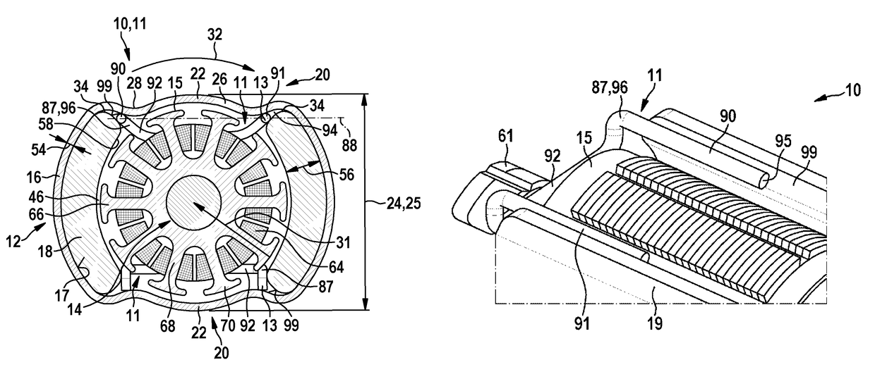
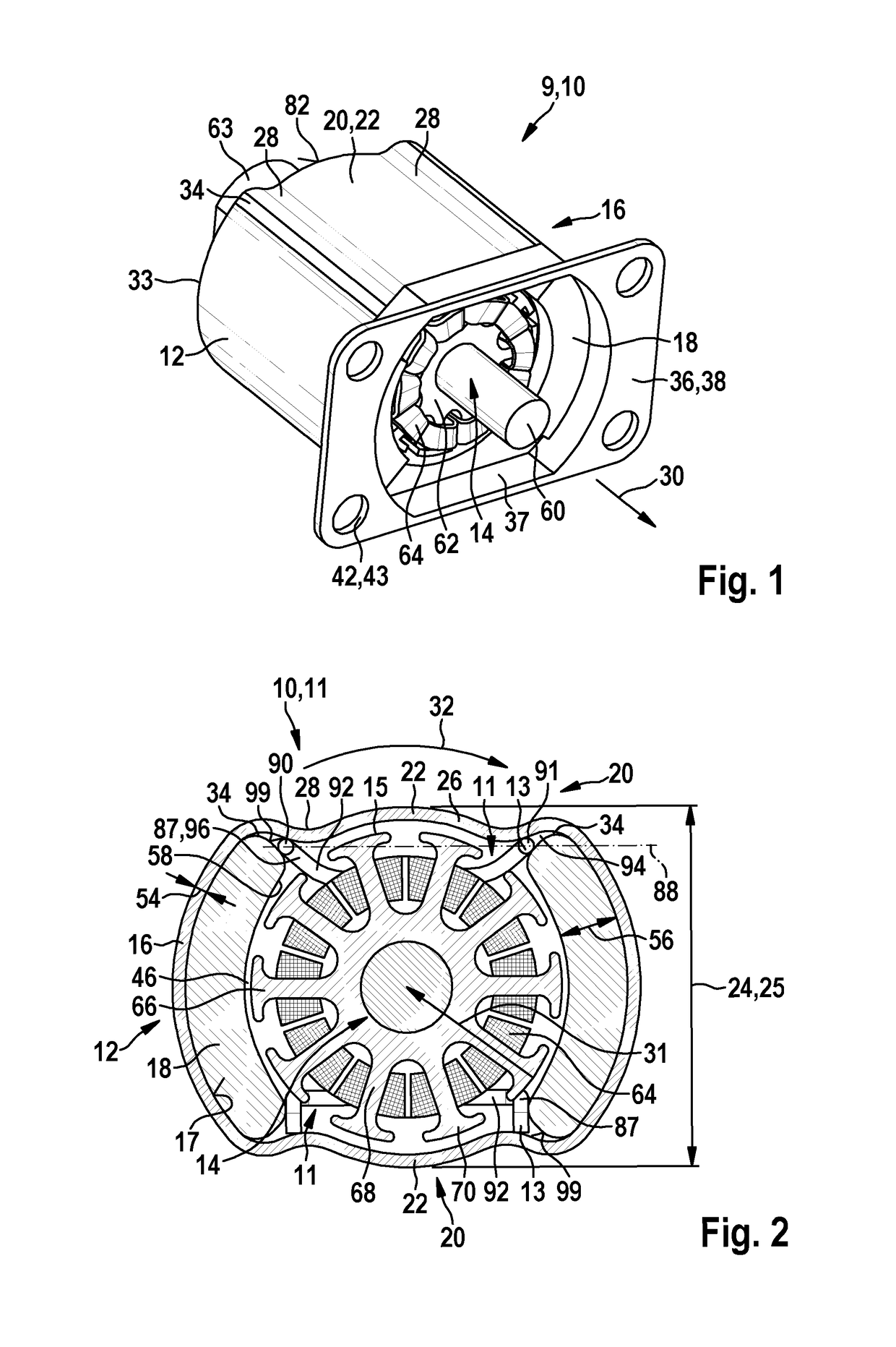
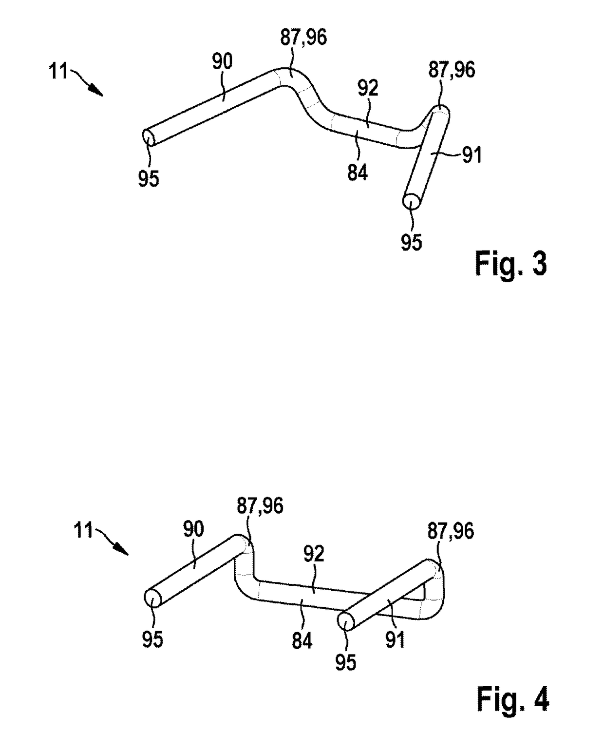
[0025]FIG. 1 shows an electrical machine 10 according to the invention which is in the form of an electric motor 11. The electric motor 11 is, for example, a constituent part of a gear mechanism / drive unit 100, as is used for adjusting a sliding roof, a window or a seat part in motor vehicles. The electrical machine 10 has a stator 12 in which two permanent magnets 18 are arranged opposite one another in a housing 16 which is in the form of a pole housing 16. Two consequent poles 22 which are situated opposite one another and are formed by the housing wall 26 of the pole housing 16 are arranged between the two permanent magnets 18 which are situated opposite one another. To this end, in each case two beads 28, which extend in the axial direction 30—preferably as far as a housing base 82 of the housing 16—are formed in flattened regions 20 of the pole housing 16. The consequent pole 22 is in the form of a curved pole housing wall 26 between the two beads 28 in the circumferential dir...


PUM


Abstract

The invention relates to a magnet-retaining spring (11), to an electric machine (10) containing such a magnet-retaining spring, and to a method for producing the electric machine (10), in particular for the motorized adjustment of moving parts in a motor vehicle, wherein the magnet-retaining spring (11) has a first leg (90) and a second leg (91), which are connected to each other by means of a bow (92), and the first and second legs (91, 92) span a plane (88) in space, wherein the bow (92) protrudes from the spanned plane (88).

Description

BACKGROUND OF THE INVENTION[0001]The invention proceeds from a magnet-retaining spring, and also an electrical machine containing a magnet-retaining spring of this kind, and also a method for producing the electrical machine.[0002]U.S. Pat. No. 4,372,035 has disclosed an electric motor in which two permanent magnets which are situated opposite one another and two so-called consequent poles between said two permanent magnets are arranged in a pole housing. In order to form the consequent poles, a contour is formed in the pole housing wall, the arcuate inner face of said contour being at the same distance from the rotor as the shell-like permanent magnets. Magnet-retaining springs which press the permanent magnets against the housing wall by means of a spring force in order to fasten said permanent magnets are known for fastening permanent magnets in the pole housing. DE 102007004873 A1 describes, for example, a magnet-retaining spring of this kind, in which shafts are formed on the t...

Claims


Application Information

Patent Timeline
Patent Type & Authority Patents(United States)
IPC IPC(8): H02K1/17H02K23/04H02K15/03H02K1/18
CPCH02K1/185H02K23/04H02K15/03H02K1/17
Inventor MILI, TAREK
Owner ROBERT BOSCH GMBH
Why Eureka
Try Eureka