
Fluid-filled damper for gas bearing assembly

Active Publication Date: 2018-09-04
GENERAL ELECTRIC CO
View PDF96 Cites 6 Cited by
  • Summary
  • Abstract
  • Description
  • Claims
  • Application Information

AI Technical Summary

Benefits of technology

The technical effects of this patent are that it describes a new invention and its advantages. The text explains that the content of the patent is meant to make it easy for R&D personnel to understand the invention. The goal is to make the patent text useful for those working in the field of innovation.

Problems solved by technology

These rotor assemblies have a mass generating a constant static force due to gravity, and also generate a dynamic force due to, e.g., imbalances in the rotor assembly during operation.

Method used


Image

  • Fluid-filled damper for gas bearing assembly
  • Fluid-filled damper for gas bearing assembly
  • Fluid-filled damper for gas bearing assembly

Examples


Embodiment Construction

[0025]Reference will now be made in detail to present embodiments of the invention, one or more examples of which are illustrated in the accompanying drawings. The detailed description uses numerical and letter designations to refer to features in the drawings. Like or similar designations in the drawings and description have been used to refer to like or similar parts of the invention.

[0026]As used herein, the terms “first”, “second”, and “third” may be used interchangeably to distinguish one component from another and are not intended to signify location or importance of the individual components.

[0027]The terms “upstream” and “downstream” refer to the relative direction with respect to fluid flow in a fluid pathway. For example, “upstream” refers to the direction from which the fluid flows, and “downstream” refers to the direction to which the fluid flows.

[0028]Generally, the present disclosure is directed to a gas-lubricated bearing assembly for a gas turbine engine and method o...


PUM


Abstract

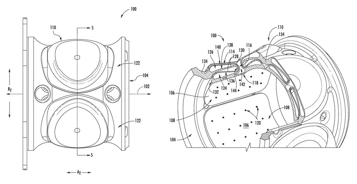
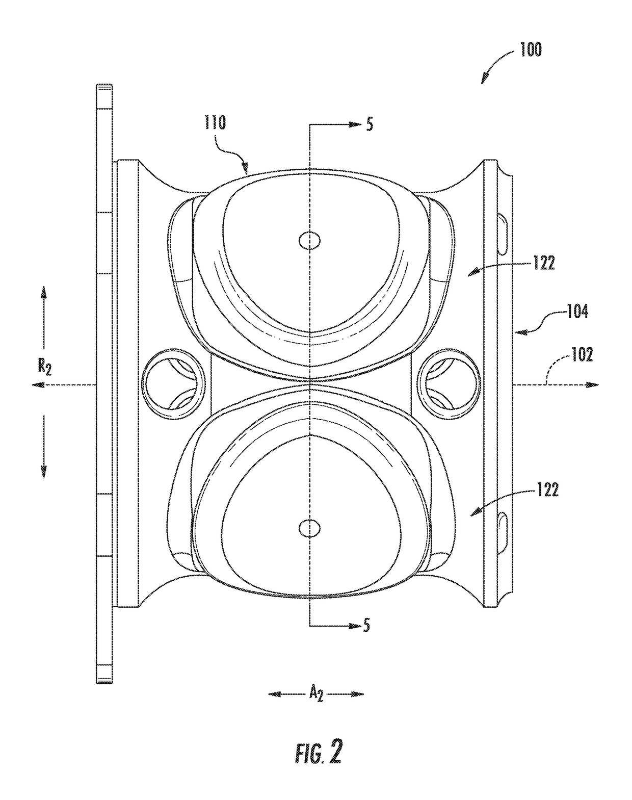
The present disclosure is directed to a gas-lubricated bearing assembly for a gas turbine engine and method of damping same. The bearing assembly includes a bearing pad for supporting a rotary component and a bearing housing attached to or formed integrally with the bearing pad. The bearing housing includes a first fluid damper cavity, a second fluid damper cavity in restrictive flow communication with the first fluid damper cavity via a restrictive channel configured as a clearance gap, and a damper fluid configured within the first and second fluid damper cavities. More specifically, the damper fluid of the present disclosure is configured to withstand the high temperature environment of the engine. Thus, the bearing housing is configured to transfer the damper fluid from the first fluid damper cavity to the second fluid damper cavity via the restrictive channel in response to a force acting on the bearing pad.

Description

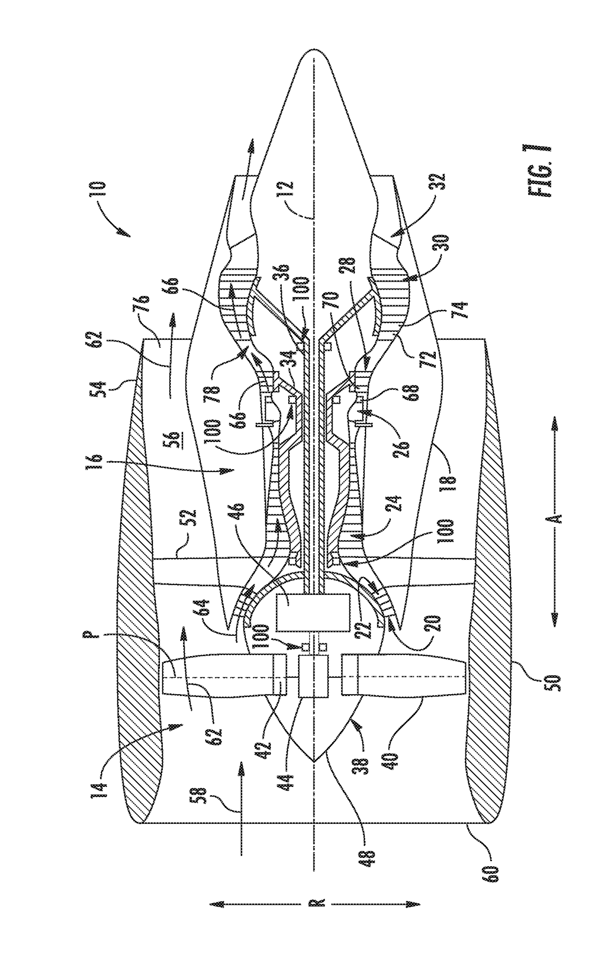
FIELD OF THE INVENTION[0001]The present subject matter relates generally to a bearing assembly, and more particularly to a fluid-filled damper for a gas bearing assembly that may be used in a gas turbine engine and methods of filling same.BACKGROUND OF THE INVENTION[0002]A gas turbine engine generally includes a fan and a core arranged in flow communication with one another. Additionally, the core of the gas turbine engine general includes, in serial flow order, a compressor section, a combustion section, a turbine section, and an exhaust section. In operation, air is provided from the fan to an inlet of the compressor section where one or more axial compressors progressively compress the air until it reaches the combustion section. Fuel is mixed with the compressed air and burned within the combustion section to provide combustion gases. The combustion gases are routed from the combustion section to the turbine section. The flow of combustion gasses through the turbine section driv...

Claims


Application Information

Patent Timeline
Patent Type & Authority Patents(United States)
IPC IPC(8): F16C17/02F16C32/06F16C25/04F16C27/02F01D25/16F16F9/10F16F15/023F16C17/03
CPCF01D25/164F16C17/035F16C25/04F16C27/02F16C32/0603F16C32/0622F16F15/0237F16F9/10F16F2228/008F05D2220/32F05D2240/53F16C2360/23F16F2222/12F16F2224/04F16F2230/105
Inventor ERTAS, BUGRA HANMOOK, JOSHUA TYLERBELLARDI, JASON JOSEPH
Owner GENERAL ELECTRIC CO
Learn More