Bulk material container, sleeve and method of assembly

Active Publication Date: 2018-09-04
RMC JONES
View PDF57 Cites 17 Cited by
  • Summary
  • Abstract
  • Description
  • Claims
  • Application Information

AI Technical Summary

Benefits of technology

This patent describes a unique bulk container system that can be used for packaging various materials. The system is made up of a forming member and a locking assembly that hold the forming member in a desired shape. The forming member is made of a lightweight, corrugated material, while the outer support sleeve is made of woven polypropylene material. The sleeve is designed to snugly engage the forming member to provide strength and support. The invention provides a solution for packaging solid, semi-solid, granular, or liquid materials in a versatile and efficient way.

Problems solved by technology

This is particularly an issue thereof when peripherally joined sidewalls of an operatively folded forming member are glued together to form a generally inelastic joint.
Random matching of forming members with sleeves during assembly has been an issue in the manufacture and assembly of such containers.
Such sleeve tolerance variances can cause an issue when, for example, an outer sleeve manufactured to its maximum inside circumferential tolerance is matched in operative overlying engagement with a forming member that is manufactured to its minimum outer circumferential tolerance.
In such instances, the sleeve does not initially snugly engage the outer surface of the forming member, which can lead to rupture of the forming member as it expands from applied forces by the bulk material before the overlying sleeve can fully counteract the radial bulk material forces applied to and through the forming member.
Recognizing this relative tolerance dilemma, assemblers of the containers have been prone to use labor intensive, costly steps of measuring and hand-sorting the outer sleeve and forming members to cooperatively match the sleeves and forming members to be assembled, according to their actual sizes.
Such pre-assembly forming member and sleeve sorting and matching operations are time consuming and costly functions.
Further, the preassembly sorting and matching of sleeves and forming members generally makes the container assembly process unsuitable for automation.

Method used


Image

  • Bulk material container, sleeve and method of assembly
  • Bulk material container, sleeve and method of assembly
  • Bulk material container, sleeve and method of assembly

Examples


Embodiment Construction

[0037]One embodiment of a bulk material container assembly of the type to which the present invention applies is described below with reference to FIGS. 1-8. Descriptions of alternative bulk material container embodiments, of their use and construction, of the materials that are usable to construct the container assemblies, and other alternatives applicable to the invention are described more fully in U.S. Pat. No. 6,932,266 which is fully incorporated herein by reference.

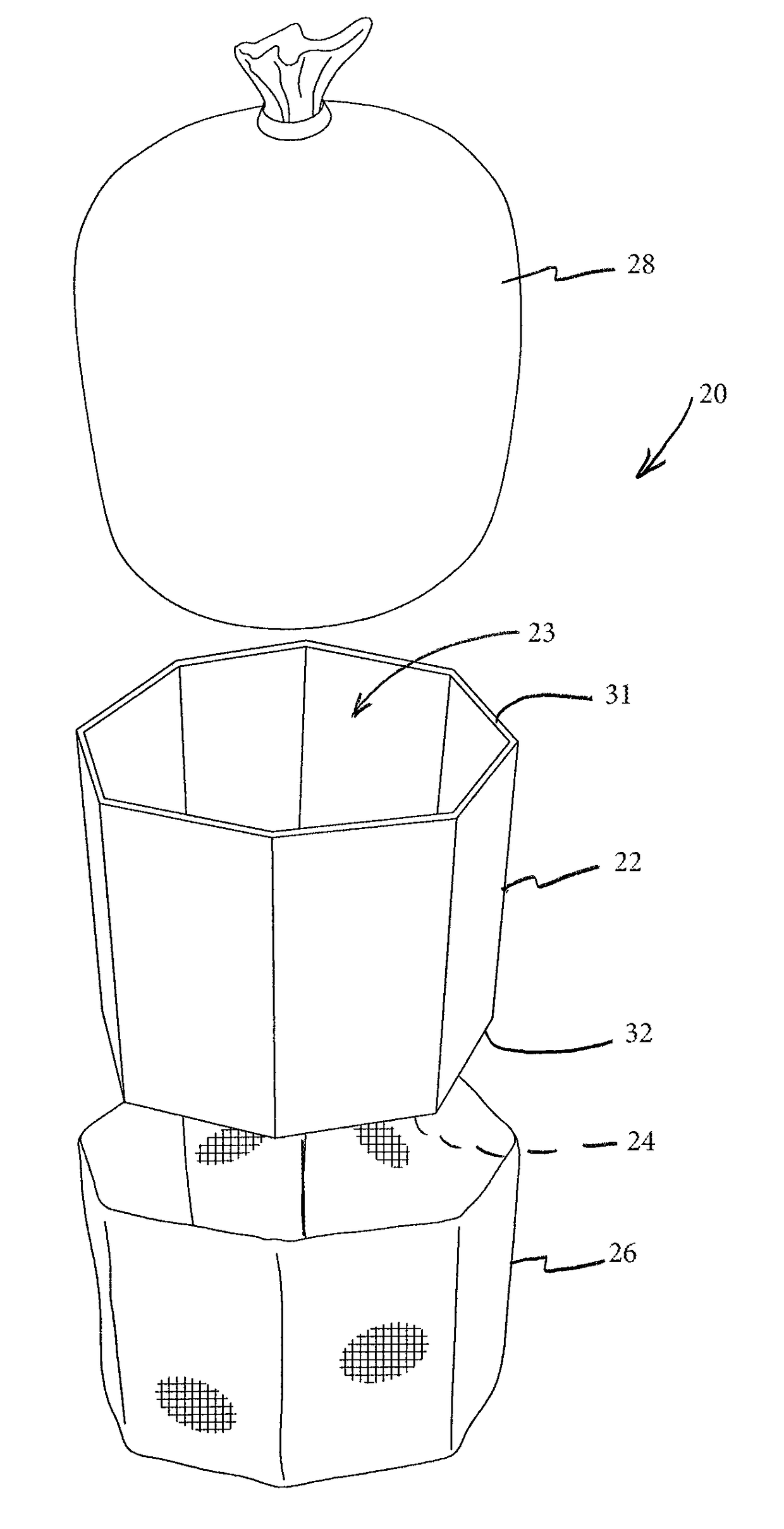
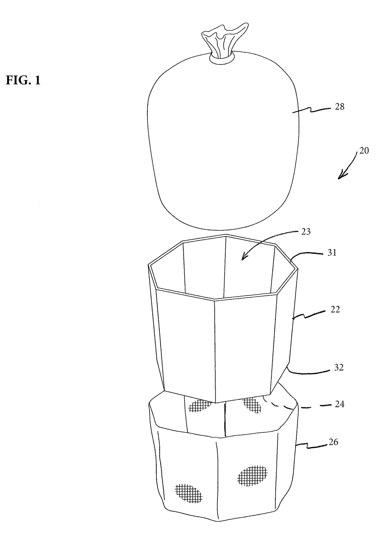
[0038]Referring to FIG. 1, a bulk material container assembly is generally illustrated at 20. For ease of description, the bulk material container assembly will hereinafter be referred to as “the container”. The container 20 generally includes a forming member 22, a locking assembly or mechanism 24, an outer support sleeve 26 and an optional inner liner 28. The forming member 22 provides a defined geometric shape and structural stability to the container, while the sleeve 26 is sized to cooperatively and snugly eng...


PUM

PropertyMeasurementUnit
Widthaaaaaaaaaa
Widthaaaaaaaaaa
Widthaaaaaaaaaa

Abstract

A collapsible bulk material container with a unique outer support sleeve and method of manufacture thereof are disclosed. The initial inner circumference of an oversized continuous woven tubular support sleeve is adjustably sized to mattingly match the outer peripheral circumference of a bulk material container forming member which it is designed to support. One or more adjustment tails are formed from the continuous sleeve material to accurately reduce the initial inner sleeve circumference to an adjusted inner circumference. The sizing operation can be performed during initial manufacture of the sleeve or prior to assembly of the sleeve to the forming member.

Description

FIELD OF THE INVENTION[0001]This invention relates generally to shipping and storage containers for bulk materials, and more particularly to such containers that use a tubular outer containment sleeve of flexible woven fiber material that snugly overlies a forming member, and which provides the primary containment strength for the container.BACKGROUND OF THE INVENTION[0002]A general description of known configurations of bulk material containers is detailed in the Background section of U.S. Pat. No. 6,932,266 entitled COLLAPSIBLE BULK MATERIAL CONTAINER, issued on Aug. 23, 2005. The U.S. Pat. No. 6,932,266 also describes a number of embodiments of improved bulk material container configurations, of the type to which the present invention is specifically directed. The U.S. Pat. No. 6,932,266 is fully incorporated herein by reference.[0003]The bulk material containers of the general type described in the U.S. Pat. No. 6,932,266 have been well received and successful in the marketplace...

Claims


Application Information

Patent Timeline
IPC IPC(8): B65D3/00B65D5/56B65D5/42B65D5/10B29C65/00B29C65/08B65D77/06B29K23/00B29L31/00
CPCB65D77/062B65D77/061B65D5/4266B65D5/10B65D5/563B29C65/08B29C66/1122B29C66/729B29C66/4322B29K2023/12B29L2031/7126B29C65/18B29C65/62B29C66/4312B29C66/71B29C66/7292B29C66/73921B65D5/029B65D5/42B65D5/445B65D5/106B65D5/62B31B2110/30B31B2120/501B31B2105/0022
Inventor JONES, ROBERT J.JONES, MICHAEL R.
Owner RMC JONES
Why Eureka
Try Eureka