
Exhaust heat recovery structure

a heat recovery structure and exhaust heat technology, applied in the direction of engines, mechanical equipment, machines/engines, etc., can solve the problems of inability to accurately acquire the temperature of the coolant in the heat exchanger, and the coolant may boil, so as to achieve excellent effect, suppress the effect of boiling the coolant effectively, and improve the engine's warm up performan

Active Publication Date: 2018-08-21
TOYOTA JIDOSHA KK
View PDF17 Cites 1 Cited by
  • Summary
  • Abstract
  • Description
  • Claims
  • Application Information

AI Technical Summary

Benefits of technology

[0007]In consideration of the circumstances described above, an object of the present invention is to provide an exhaust heat recovery structure that may suppress boiling of coolant in a heat exchanger.

Problems solved by technology

However, the technology disclosed in Patent Document 1 gives no consideration to the location at which the temperature of the coolant is sensed, and it may not be possible to accurately acquire a temperature of the coolant in the heat exchanger.
Consequently, when the temperature of the coolant in the heat exchanger rises, the coolant may boil.

Method used


Image

  • Exhaust heat recovery structure
  • Exhaust heat recovery structure
  • Exhaust heat recovery structure

Examples


first exemplary embodiment

[0024]—

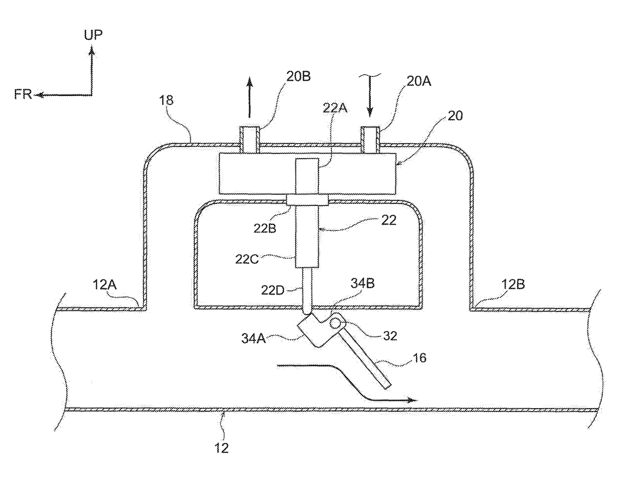
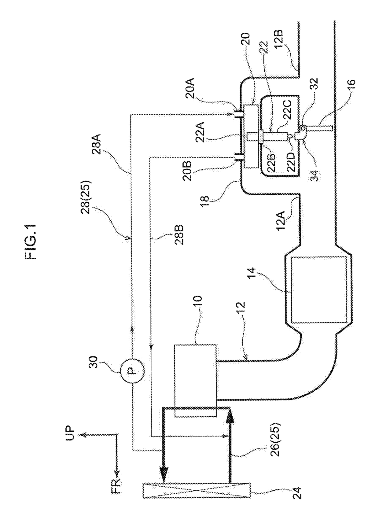
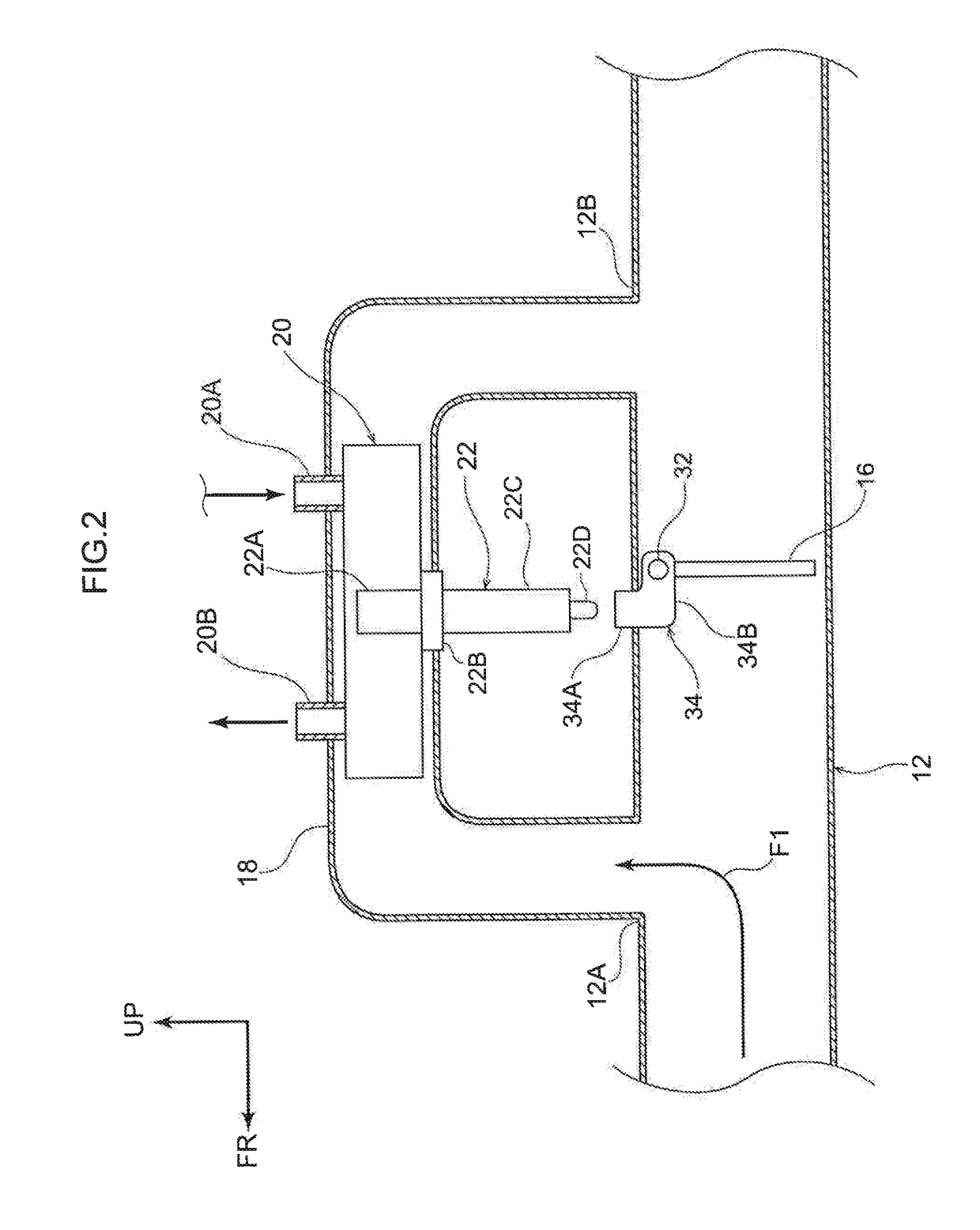
[0025]An exhaust heat recovery structure according to a first exemplary embodiment is described with reference to FIG. 1 to FIG. 3. The arrow FR that is shown as appropriate in the drawings indicates the vehicle front side of a vehicle in which the exhaust heat recovery structure is employed, the arrow UP indicates the vehicle upper side, and the arrow RH indicates the vehicle right side. In the following descriptions, where the directions front, rear, up, down, left and right are used without being particularly specified, the same represent the front and rear in the vehicle front-and-rear direction, up and down in the vehicle up-and-down direction, and left and right if facing in the running direction. For convenience of depiction, pipes are shown in section in the drawings.

[0026]As shown in FIG. 1, an exhaust system in which the exhaust heat recovery structure according to the present exemplary embodiment is employed has a structure in which a first pipe 12 is connected to ...

second exemplary embodiment

[0059]—

[0060]Now, an exhaust heat recovery structure according to a second exemplary embodiment is described with reference to FIG. 4 to FIG. 6. Overall structure of the exhaust system is similar to the structure in FIG. 2, apart from the principal portions shown in FIG. 4 to FIG. 6. Structures that are the same as in the first exemplary embodiment are assigned the same reference numerals and, as appropriate, are not described. For convenience of explanation, a driving cam 56 and the thermostat 22 are shown in FIG. 4 and FIG. 5. In practice, however, the driving cam 56 and the thermostat 22 would be disposed to the paper surface side of the drawing relative to a first pipe 52.

[0061]As shown in FIG. 4, the exhaust heat recovery structure according to the present exemplary embodiment is a coaxial-type structure in which the first pipe 52 and a second pipe 54 are provided concentrically. The first pipe 52 extends in the vehicle front-and-rear direction. Exhaust gas from the engine flow...


PUM


Abstract

There is provided an exhaust heat recovery structure that may suppress boiling of coolant in a heat exchanger. The exhaust heat recovery structure includes a first pipe, a second pipe, a valve and a thermostat. Exhaust gas from an engine flows in the first pipe. The second pipe branches from the first pipe and a heat exchanger that exchanges heat between the coolant and exhaust gas is provided at the second pipe. The valve is provided at the first pipe or the second pipe. The valve adjusts a flow amount of exhaust gas flowing into the second pipe by opening and closing. The thermostat is equipped with a heat-sensing portion that is disposed inside the heat exchanger. When the temperature of the heat-sensing portion is high, the thermostat opens or closes the valve to reduce the flow amount of exhaust gas flowing into the second pipe.

Description

CROSS-REFERENCE TO RELATED APPLICATION[0001]This application is based on and claims priority under 35 USC 119 from Japanese Patent Application No. 2015-126882 filed on Jun. 24, 2015, which is incorporated by reference herein.BACKGROUND[0002]Technical Field[0003]The present invention relates to an exhaust heat recovery structure.[0004]Related Art[0005]An exhaust heat recovery structure is known that heats a coolant and accelerates warm-up of an engine, by a heat exchanger being disposed on an exhaust pipe through which exhaust gas from the engine flows and heat being exchanged between coolant that flows in the heat exchanger and the exhaust gas. A configuration of this exhaust heat recovery structure is disclosed in Japanese Patent Application Laid-Open (JP-A) No. 2006-312884 (Patent Document 1), which is equipped with a bypass pipe through which exhaust gas flows, a valve body (valve) provided inside the bypass pipe, and a branch pipe that branches from the bypass pipe and is connec...

Claims


Application Information

Patent Timeline
Patent Type & Authority Patents(United States)
IPC IPC(8): F01N3/02F01N3/28F01N5/02
CPCF01N5/02F01N3/2889F01N2240/02Y02T10/16F01N2410/03F01N2410/06F01N2240/36Y02T10/12F02G5/02F28D21/0003
Inventor MURATA, TOSHIONAKAGAWA, TADASHI
Owner TOYOTA JIDOSHA KK
Learn More