Multi-band, multi-polarized wireless communication antenna
a multi-polarized, wireless communication technology, applied in the direction of antennas, antenna details, polarised antenna unit combinations, etc., can solve the problem of difficult to design an antenna that satisfies, and achieve the effect of stable radiation characteristic, optimized size and optimized structur
- Summary
- Abstract
- Description
- Claims
- Application Information
AI Technical Summary
Benefits of technology
Problems solved by technology
Method used
Image
Examples
first embodiment
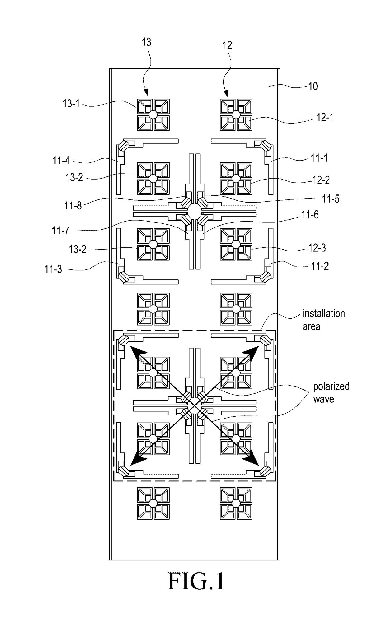
[0030]FIG. 1 is a plane structure view of a multi-band multi-polarized wireless communication antenna according to the present invention, FIG. 2 is a perspective view of a wireless communication antenna, and FIGS. 3 and 4 are characteristic graphs of a first radiation module in the wireless communication antenna of FIG. 1 and show an S-parameter characteristic and a radiation pattern characteristic, respectively.
[0031]Referring to FIGS. 1 to 4, an antenna according to the first embodiment of the present invention has a structure in which one or more first radiation modules 11 (11-1, 11-2, 11-3, 11-4, 11-5, 11-6, 11-7, 11-8) of a first frequency band (e.g., 700-900 MHz bands), which is a relatively low frequency band, and one or more second and third radiation modules 12 and 13 of a second frequency band (e.g., about 2 GHz band) and a third frequency band (e.g., about 2.5 GHz band), which are relatively high frequency bands, are arranged on one reflector 10. At this time, each of the...
second embodiment
[0049]Examining the structure of the second embodiment illustrated in FIGS. 10 to 13, it can be known that two kinds of radiation modules (i.e., the first radiation module and the 1-2th radiation module) are combined according to any configuration ratio in order to implement an antenna array of the same band, i.e. of the first band. Here, when one kind of radiation module (i.e., the 1-2th radiation module) is designed to have a wide horizontal beam width (70 degrees or more) characteristic and the other kind radiation module (i.e., the first radiation module) is designed to have a narrow horizontal width (60 degrees or less) characteristic, it is possible to implement a desired horizontal beam width by adjusting the configuration ratio of the two kinds of radiation modules and to relatively easily design the form of a radiation pattern in a limited space.
[0050]FIG. 14 is a plane structure view of a multi-band multi-polarized wireless communication antenna according to the third embo...
third embodiment
[0052]Here, in the structure of the third embodiment illustrated in FIG. 14, the multiple radiation elements 24-1, 24-2, 25-1, 25-2, 26-1, 26-2, 27-1, and 27-2, which form the first radiation module, are configured to be divided into, for example, 1-1th and 1-2th radiation elements 24-1 and 24-2, 2-1th and 2-2th radiation elements 25-1 and 25-2, 3-1th and 3-2th radiation elements 26-1 and 26-2, and 4-1th and 4-2th radiation elements 27-1 and 27-2, respectively, on the basis of a generated polarized wave.
[0053]More specifically, in the above-described structure, the 1-1th and 1-2th radiation elements 24-1 and 24-2 are implemented so as to be linked with each other to be fed and are configured to generate a first polarized wave. Similarly, the 2-1th and 2-2th radiation elements 25-1 and 25-2 are configured to generate a second polarized wave, the 3-1th and 3-2th radiation elements 26-1 and 26-2 are configured to generate a third polarized wave, and the 4-1th and 4-2th radiation elemen...
PUM
 Abstract
Description
Claims
Application Information
 - R&D
- Intellectual Property
- Life Sciences
- Materials
- Tech Scout
- Unparalleled Data Quality
- Higher Quality Content
- 60% Fewer Hallucinations
Browse by: Latest US Patents, China's latest patents, Technical Efficacy Thesaurus, Application Domain, Technology Topic, Popular Technical Reports.
© 2025 PatSnap. All rights reserved.Legal|Privacy policy|Modern Slavery Act Transparency Statement|Sitemap|About US| Contact US: help@patsnap.com


