
Dual camera module and method for controlling the same

a technology of camera modules and camera bodies, applied in the direction of camera focusing arrangement, instruments, printers, etc., can solve the problems of inability to precisely sense the movement the error in the auto-focus position of the lens, and the signal interference between the camera modules, so as to reduce the natural frequency of the spring, reduce the auto-focus time, and avoid the effect of auto-focus

Active Publication Date: 2018-07-17
LG ELECTRONICS INC
View PDF26 Cites 0 Cited by
  • Summary
  • Abstract
  • Description
  • Claims
  • Application Information

AI Technical Summary

Benefits of technology

This approach effectively cancels signal interference between cameras, ensuring precise and fast auto-focus capabilities by coordinating camera operations based on sensor type and incorporating stabilization and damping mechanisms.

Problems solved by technology

When a camera module that includes a hall sensor is applied to the dual camera module, a magnetic force of the camera module acts on its adjacent camera module, whereby signal interference occurs between the camera modules.
As a result, a movement position of the lens cannot be sensed exactly, and an error in the auto-focus position of the lens occurs.

Method used


Image

  • Dual camera module and method for controlling the same
  • Dual camera module and method for controlling the same
  • Dual camera module and method for controlling the same

Examples


first embodiment

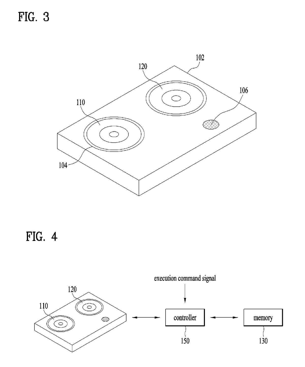
[0093]FIGS. 3 to 5 are diagrams illustrating a driving mode of a dual camera module according to the present invention.

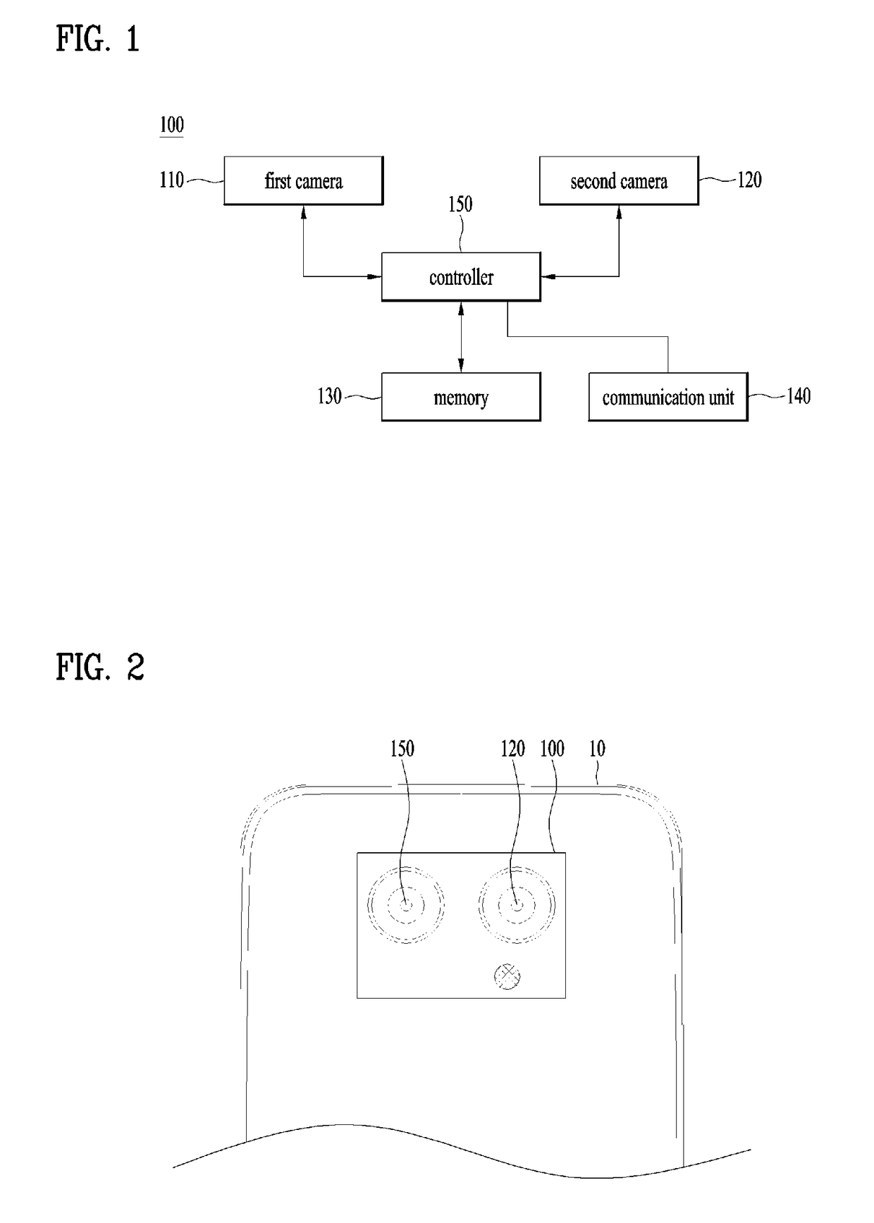
[0094]As shown in FIG. 3, the dual camera module according to the first embodiment of the present invention is a fixed type, in which the first and second cameras 110 and 120 are fixed within a groove 104 of a body unit 102.

[0095]In this case, the body unit 102 of the dual camera module may additionally be provided with a light emitting module 106.

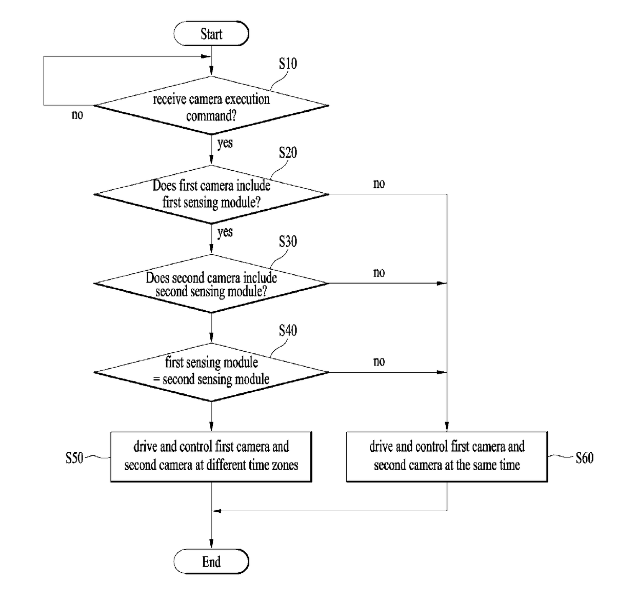
[0096]As shown in FIG. 4, in the fixed type dual camera module, if a camera execution command is received, the controller 150 may identify whether the first camera 110 includes the first sensing module that senses movement of the first lens module, and if the first camera 110 includes the first sensing module, may identify whether the second camera 120 includes the second sensing module that senses movement of the second lens module.

[0097]In this case, when identifying whether the first camera 110 includes the first sensin...

second embodiment

[0110]FIGS. 6 to 8 are diagrams illustrating a driving mode of a dual camera module according to the present invention.

[0111]As shown in FIG. 6, the dual camera module according to the second embodiment of the present invention is a detachable type, in which the first and second cameras 110 and 120 are detached from a groove 104 of a body unit 102 or installed in the groove 104 of the body unit 102.

[0112]In this case, the body unit 102 of the dual camera module may additionally be provided with a light emitting module 106.

[0113]As shown in FIG. 7, in the fixed type dual camera module, if a camera execution command is received, the controller 150 may identify whether the first camera 110 includes the first sensing module that senses movement of the first lens module, and if the first camera 110 includes the first sensing module, may identify whether the second camera 120 includes the second sensing module that senses movement of the second lens module.

[0114]In this case, when identif...


PUM


Abstract

A dual camera module that includes a voice coil motor actuator and a method for controlling the same are disclosed. The dual camera module comprises a first camera including a first lens module; a second camera including a second lens module, arranged to adjoin the first camera; and a controller for controlling the first camera and the second camera, wherein the controller identifies whether the first camera includes a first sensing module for sensing movement of the first lens module if a camera execution command is received, identifies whether the second camera includes a second sensing module for sensing movement of the second lens module if the first camera includes the first sensing module, identifies whether the first sensing module of the first camera and the second sensing module of the second camera have the same type as each other if the second camera includes the second sensing module, and controls the first camera and the second camera at different time zones if the first sensing module and the second sensing module have the same types as each other.

Description

CROSS REFERENCE TO RELATED APPLICATIONS[0001]This application claims priority under 35 U.S.C. § 119 to U.S. Application No. 62 / 331,444, filed in U.S. on 4 May 2016 and Korean Application No. 10-2016-0117823, filed in Korea on 13 Sep. 2016, which are hereby incorporated in its entirety by reference as if fully set forth herein.BACKGROUND OF THE INVENTIONField of the Invention[0002]The present invention relates to a dual camera module, and more particularly, to a dual camera module, which includes a voice coil motor actuator, and a method for controlling the same.Discussion of the Related Art[0003]Recently, with the development of technology, mobile terminals having multiple functions integrated with high density are being released, and tend to be miniaturized and lightweight to be suitable for a mobile condition in spite of a variety of functions.[0004]Therefore, a camera module installed in a mobile terminal such as a cellular phone and a laptop computer also tends to be miniaturize...

Claims


Application Information

Patent Timeline
Patent Type & Authority Patents(United States)
IPC IPC(8): H04N5/232H04N5/247G02B7/28G02B27/64G02B7/08H04N5/225G03B13/36H04M1/02H04N23/90
CPCH04N5/23287G02B7/08G02B7/28G02B27/646G03B13/36H04N5/2258H04N5/23248H04N5/23258H04N5/247H04N5/2253H04N5/2257H04M1/0264H04N23/54H04N23/50H04N23/55H04N23/67H04N23/6815G03B3/10G03B2205/0053H04N23/45H04N23/57H04N23/68H04N23/6812H04N23/90H04N23/687
Inventor KANG, HYUNGJOOKWON, SUNGDUKWON, YOUNGMANHONG, SAMNYOLLEE, JAYONG
Owner LG ELECTRONICS INC
Learn More