
MR imaging with signal suppression of a spin series

a technology of signal suppression and mr imaging, applied in the field of mr imaging with signal suppression of a spin series, can solve the problems of increasing measurement duration, affecting diagnosis, and relatively long preparation time, and achieve good signal suppression

Active Publication Date: 2018-07-17
SIEMENS HEALTHCARE GMBH
View PDF12 Cites 3 Cited by
  • Summary
  • Abstract
  • Description
  • Claims
  • Application Information

AI Technical Summary

Benefits of technology

[0052]For such techniques, it can be necessary to use a relatively wide spatial domain profile of the inversion profile along the slice selection direction (slice thickness). This can in principle involve disadvantageous effects. For example, for a relatively wide slice thickness it can be necessary to use relatively small amplitudes of the gradient pulses; this can in turn increase a sensitivity relative to inhomogeneities of the basic magnetic field. This can be the case because the gradient field strength is small in comparison to deviations of the basic magnetic field strength. Furthermore, the maximum amplitude of the inversion pulse is also limited, for instance for reasons of biological compatibility of the microwave exposure involved with the radiation of the inversion pulse. In particular, typical limited limit values of the specific absorption rate (SAR) are not to be exceeded.
[0053]Therefore, it can be particularly advantageous if the inversion pulse widens asymmetrically along that direction in which the residual magnetization of the second spin species would otherwise occur due to the frequency shift of the inversion pulse. In particular, the asymmetry can correlate with the strength of the frequency shift. For example, the asymmetry be chosen to be greater (lesser) the larger (smaller) the frequency shift between the two spin species.
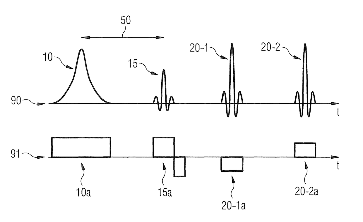
[0054]In the preceding, techniques were explained for the acquisition of MR data according to different aspects. For example, by means of such techniques the effect of a particularly good suppression of the signal of the second spin species in the MR data can be achieved. Such techniques described in the preceding can also be designated as a STIR-SSGR technique. For example, the combination of inversion pulse and excitation pulse can thus be designated as the STIR portion of the combined STIR-SSGR technique. The combination of excitation pulse with the first gradient pulse and with the at least one manipulation pulse can also be designated as the SSGR portion of the combined STIR-SSGR technique. A complete or a partial SSGR technique can be used depending on how large the difference is chosen to be between the amplitudes of the first and second gradient pulse, i.e. how strong the frequency shift turns out to be a complete (partial) SSGR technique can be present if the spatial domain profiles of the excitation pulse and of the at least one manipulation pulse are completely (partially) separate for the second spin species, i.e. have no (a partial) overlap.
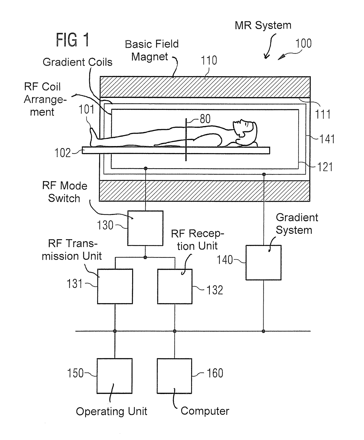
[0055]According to one aspect, the invention concerns an MR system to acquire MR data of a first spin species in a slice of an examination subject. The MR data include a signal of the first spin species. In the MR data, a signal of a second spin species is suppressed. The first spin species and the second spin species have a frequency shift relative to one another. The first spin species and the second spin species have different spin-lattice relaxation times. The MR system has a transmission unit and a gradient system that are designed in order to implement the following steps: apply an inversion pulse that acts on a longitudinal magnetization of the first spin species and the second spin species in the slice; after a predetermined time period that coincides with the spin-lattice relaxation time of the second spin species, apply an excitation pulse with an associated first gradient pulse that generates a transverse magnetization; apply at least one manipulation pulse, respectively with an associated second gradient pulse to generate at least one echo of the transverse magnetization of the first spin species, wherein an amplitude of the at least one second gradient pulse is different than an amplitude of the first gradient pulse. The MR system furthermore has a reception unit that is designed in order to acquire MR data in the entire slice. In a partial region of the slice in which the inversion pulse has different flip angles for the first spin species and the second spin species due to the frequency shift, at least one of the at least one manipulation pulses has a smaller flip angle for the second spin species than for the first spin species.
[0056]According to this aspect of the invention, the MR system can be designed in order to execute a method to acquire MR data according to a further aspect.
[0057]For such an MR system, effects can be achieved that are comparable to the effects that can be achieved for the method to acquire MR data according to a further aspect.

Problems solved by technology

Moreover, in specific imaging methods, fat signals lead to artifacts that hinder the diagnosis.
The STIR technique can require relatively long preparation times, which can increase the measurement duration.
Moreover, an application of the SSGR technique is often limited to spin echo imaging.
This can limit the clinical evaluation capability.
This can also limit the evaluation capability of corresponding MR images.
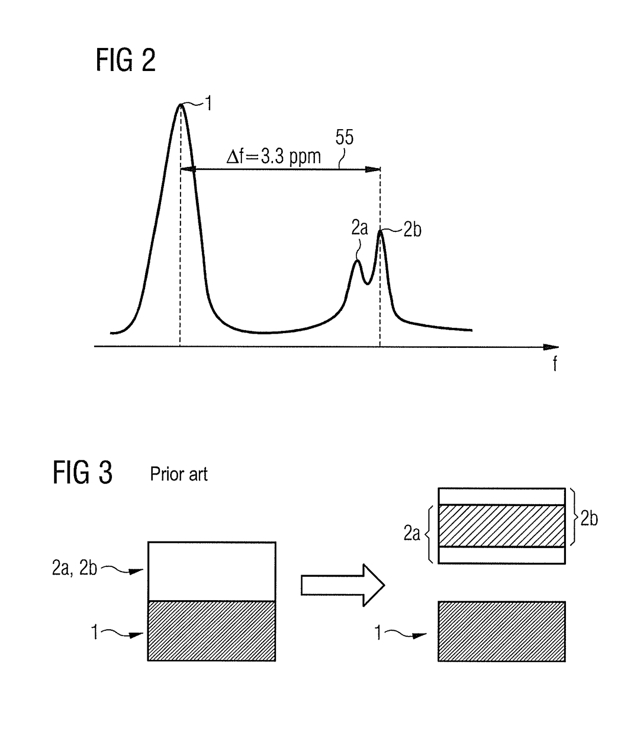
However, such combined STIR-SSGR techniques have the disadvantage that suppression of the spin species to be suppressed is often incomplete.

Method used


Image

  • MR imaging with signal suppression of a spin series
  • MR imaging with signal suppression of a spin series
  • MR imaging with signal suppression of a spin series

Examples


Embodiment Construction

[0107]In the following, the present invention is explained in detail using preferred embodiments with reference to the drawings. In the figures, identical reference characters designate identical or similar elements. The figures are schematic representations of various embodiments of the invention. Elements shown in the figures are not necessarily represented true to scale. Rather, the different elements shown in the figures are rendered such that their function and general purpose are understandable to those skilled in the art. Connections and couplings that are shown in the figures between functional units and elements can also be implemented as indirect connections or couplings. A connection or coupling can be implemented in a hardwired or wireless manner. Functional units can be implemented as hardware, software or as a combination of hardware and software.

[0108]In the following, techniques are described that are used for an MR measurement (data acquisition) of a first spin spec...


PUM


Abstract

In a magnetic resonance measurement sequence, an inversion pulse is applied that acts on a longitudinal magnetization of a first spin species and a second spin species, for example on a water portion and a fat portion. An excitation pulse is applied after a predetermined time period. At least one manipulation pulse is subsequently applied, respectively with associated gradient pulse.

Description

BACKGROUND OF THE INVENTION[0001]Field of the Invention[0002]The present invention concerns a method to acquire magnetic resonance data of a first spin species and a magnetic resonance system, and in particular concerns the suppression of a signal of a second spin species in the magnetic resonance data.[0003]Description of the Prior Art[0004]Within the scope of magnetic resonance (MR) data acquisition of signals elicited from nuclear spins, a longitudinal magnetization is polarized in a basic magnetic field. The longitudinal magnetization is excited by an excitation pulse so that a transverse magnetization arises. This can be specifically manipulated, for example dephased and rephased so that an echo is produced. This echo can be detected as a signal in order to provide MR data. Signals from proton nuclear spins are often measured. A spatial resolution of the MR data can be generated by application of gradient pulses that produce spatially variable gradient fields.[0005]Within the s...

Claims


Application Information

Patent Timeline
Patent Type & Authority Patents(United States)
IPC IPC(8): G01R33/483G01R33/50A61B5/055G01R33/561G01R33/54G01R33/56G01R33/565
CPCG01R33/4833A61B5/055G01R33/50G01R33/561G01R33/5607G01R33/543G01R33/56527G01R33/5602
Inventor FEIWEIER, THORSTEN
Owner SIEMENS HEALTHCARE GMBH
Learn More