Resonant DC-DC power converter assembly
a power converter and dc power supply technology, applied in the direction of ac-dc conversion, efficient power electronics conversion, electric variable regulation, etc., can solve the problems of significant suppression of emi emissions, unsatisfactory emi emissions, and significant decrease of ripple voltage levels on the dc power supply voltage of the converter assembly, so as to reduce manufacturing costs, reduce component count, and reduce the effect of siz
- Summary
- Abstract
- Description
- Claims
- Application Information
AI Technical Summary
Benefits of technology
Problems solved by technology
Method used
Image
Examples
first embodiment
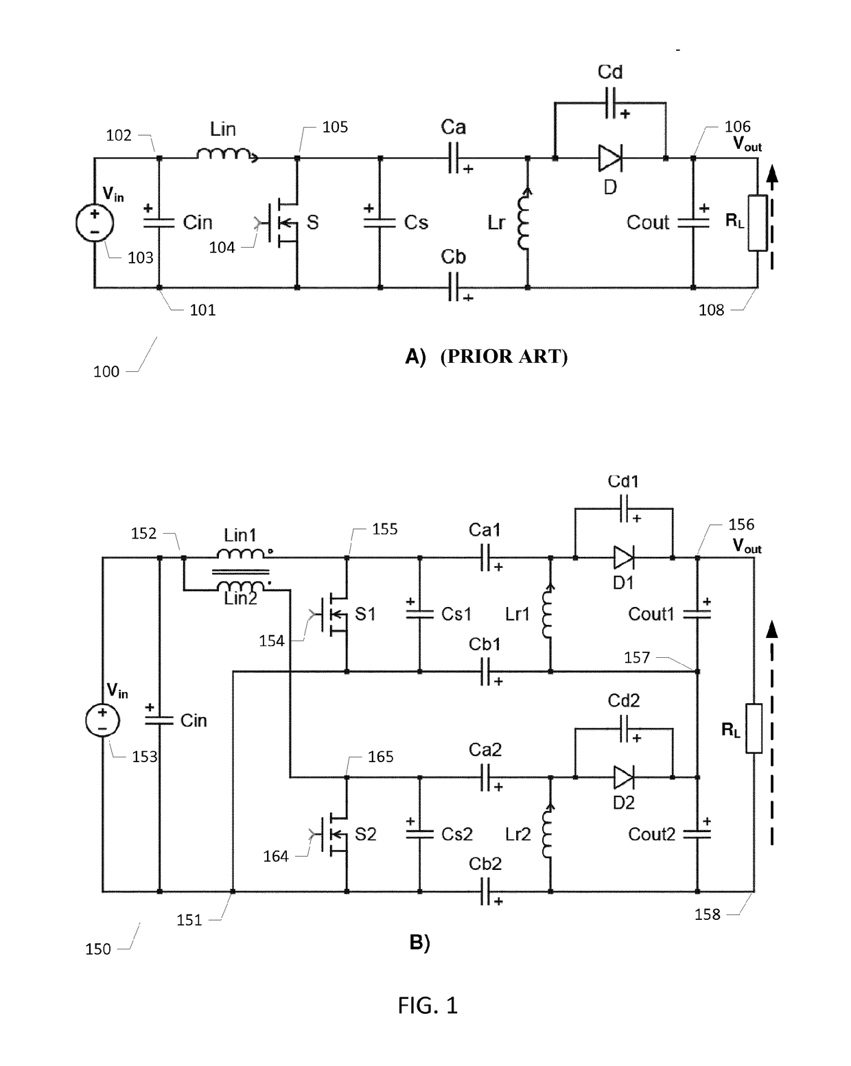
[0051]FIG. 1B) is a simplified electrical circuit diagram of a resonant DC-DC power converter assembly 150 in accordance with the invention comprising a pair of magnetically coupled isolated SEPIC DC-DC power converters. The resonant DC-DC power converter assembly 150 comprises a first isolated SEPIC converter built around semiconductor switch S1 and a second isolated SEPIC converter built around semiconductor switch S2. The first and second SEPIC DC-DC power converters are interconnected, or mutually coupled, via first and second magnetically coupled input inductors Lin1 and Lin2. Lin1 and Lin2 are arranged or configured to force substantially 180 degrees phase shift between resonant voltage waveform at the outputs, i.e. drain voltages in the present embodiment, of the first and second semiconductor switches S1, S2. The open dot symbol at the input inductor Lin1 and the closed dot symbol at the input inductor Lin2 indicate that the windings of these inductors are arranged to produc...
second embodiment
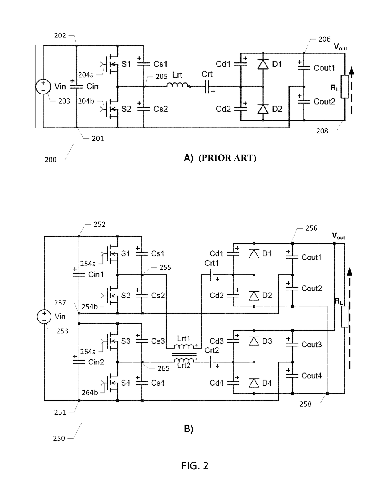
[0060]FIG. 2B) is a simplified electrical circuit diagram of a resonant DC-DC power converter assembly 250 comprising a pair of coupled resonant class DE DC-DC power converters in accordance with the invention. The resonant DC-DC power converter assembly 250 comprises a first class DE power converter built around a first controllable switch arrangement in form of a half-bridge inverter comprising first and second stacked semiconductor switches S1, S2 and a second class DE power converter built around a second controllable switch arrangement in form of a half-bridge inverter comprising third and fourth stacked semiconductor switches S3, S4. The first and second class DE power converters are interconnected, or mutually coupled, via first and second magnetically coupled inductors Lrt1 and Lrt2. Inductors Lrt1 and Lrt2 form part of the respective resonant networks of the first and second class DE power converters. The first and second magnetically coupled inductors Lrt1 and Lrt2 are arr...
third embodiment
[0070]FIG. 3B) is a simplified electrical circuit diagram of a resonant DC-DC power converter assembly 350 comprising first and second magnetically coupled isolated class E self-oscillating resonant DC-DC power converters in accordance with the invention. The resonant DC-DC power converter assembly 350 comprises a first self-oscillating class E power converter built around a first controllable switch arrangement in form of a single semiconductor switch S1 and a substantially identical second self-oscillating class E power converter built around a second controllable semiconductor switch S2. The skilled person will understand that each of the first and second self-oscillating class E power converters may be substantially identical to the above-discussed self-oscillating class E power converter 300. The semiconductor switch S1 of the first class E power converter drives a first resonant network via a driver output 355 or drain terminal. The semiconductor switch S1 is driven by a first...
PUM
 Abstract
Description
Claims
Application Information
 - R&D
- Intellectual Property
- Life Sciences
- Materials
- Tech Scout
- Unparalleled Data Quality
- Higher Quality Content
- 60% Fewer Hallucinations
Browse by: Latest US Patents, China's latest patents, Technical Efficacy Thesaurus, Application Domain, Technology Topic, Popular Technical Reports.
© 2025 PatSnap. All rights reserved.Legal|Privacy policy|Modern Slavery Act Transparency Statement|Sitemap|About US| Contact US: help@patsnap.com


