
Bending-insensitive single-mode fiber with ultra low attenuation

a single-mode fiber, ultra-low attenuation technology, applied in the direction of cladded optical fibres, instruments, optical elements, etc., can solve the problems of increasing the attenuation difficult to meet user requirements, and large rayleigh scattering of the existing g.652 fiber, so as to reduce the proportion of fluorine-doped glass, improve the bending performance of the optical fiber, and reduce the cost of manufacturing the optical fiber

Active Publication Date: 2018-07-10
YANGTZE OPTICAL FIBRE & CABLE CO LTD
View PDF16 Cites 0 Cited by
  • Summary
  • Abstract
  • Description
  • Claims
  • Application Information

AI Technical Summary

Benefits of technology

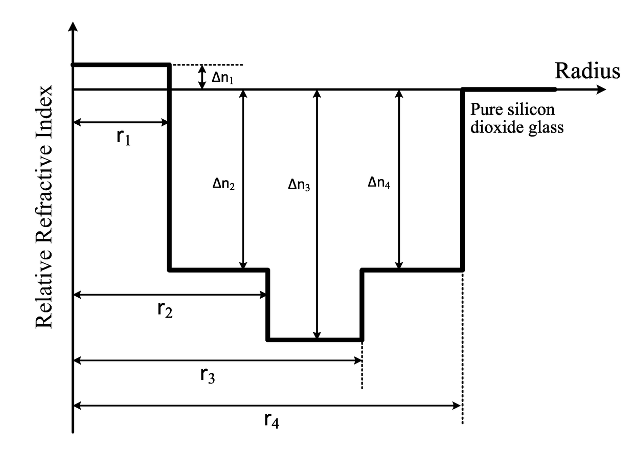
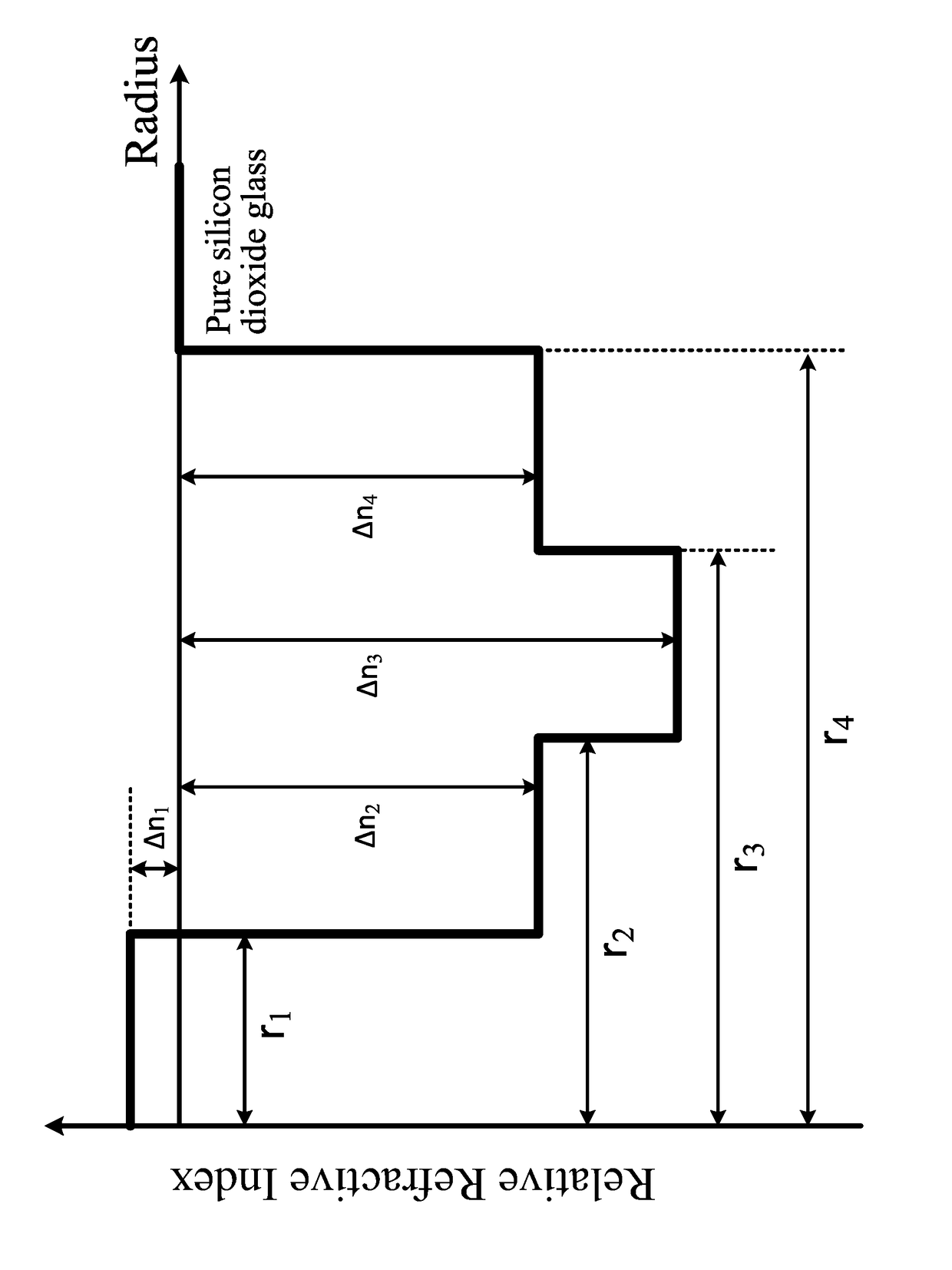
The present invention provides a single-mode fiber that is bending-insensitive and has low attenuation. The fiber has a special cross-sectional structure that reduces defects and attenuation, and good performance parameters in relevant bands. The fiber also uses a multi-step trench cladding layer structure for improved bending performance. The outer cladding layer is made of pure silica to reduce manufacturing costs. Overall, this invention offers a low-cost, high-quality single-mode fiber with excellent performance.

Problems solved by technology

In another aspect, with continuously development of FTTX in recent years, it is difficult for the performance of the existing G.652 fiber to meet users' requirements.
That is, the Ge doping in the core layer is relatively large, thereby causing a relatively large Rayleigh scattering and increasing attenuation of the optical fiber.
However, a typical step cross section structure is used in the design, instead of using a trench cladding layer design to optimize bending of the optical fiber, and Ge is not used for doping in the core layer thereof, which may therefore cause viscosity mismatch during preparation of the perform.
In addition, the attenuation and bending ability thereof are relatively poor.
Therefore, a heretofore unaddressed need exists in the art to address the aforementioned deficiencies and inadequacies.

Method used


Image

  • Bending-insensitive single-mode fiber with ultra low attenuation
  • Bending-insensitive single-mode fiber with ultra low attenuation
  • Bending-insensitive single-mode fiber with ultra low attenuation

Examples


Embodiment Construction

[0033]The invention will now be described more fully hereinafter with reference to the accompanying drawings, in which exemplary embodiments of the invention are shown. This invention may, however, be embodied in many different forms and should not be construed as limited to the embodiments set forth herein. Rather, these embodiments are provided so that this disclosure will be thorough and complete, and will fully convey the scope of the invention to those skilled in the art. Like reference numerals refer to like elements throughout.

[0034]The terms used in this specification generally have their ordinary meanings in the art, within the context of the invention, and in the specific context where each term is used. Certain terms that are configured to describe the invention are discussed below, or elsewhere in the specification, to provide additional guidance to the practitioner regarding the description of the invention. For convenience, certain terms may be highlighted, for example...


PUM


Abstract

A bending-insensitive single-mode fiber with ultralow attenuation includes a core layer and cladding layers. The cladding layers includes an inner cladding layer surrounding the core layer, a trench cladding layer surrounding the inner cladding layer, an auxiliary outer cladding layer surrounding the trench cladding layer, and an outer cladding layer surrounding the auxiliary cladding layer. The core layer has a radius of 3.0 to 3.9 μm and a relative refractive index of −0.04% to 0.12%. The inner cladding layer has a radius of 8 to 14 μm and a relative refractive index −0.35% to −0.10%. The trench cladding layer has a radius of 14 to 20 μm and a relative refractive index of −0.6% to −0.2%. The auxiliary outer cladding layer has a radius of 35 to 50 μm and a relative refractive index of −0.4% to −0.15%. The outer cladding layer is a pure silica glass layer.

Description

CROSS-REFERENCE TO RELATED APPLICATIONS[0001]This application is a continuation application of International Patent Application No. PCT / CN2015 / 096115, filed Dec. 1, 2015, which itself claims priority to Chinese Patent Application No. 201510206222.3, filed Apr. 28, 2015 in the State Intellectual Property Office of P.R. China, which are hereby incorporated herein in their entireties by reference.FIELD OF THE INVENTION[0002]The present invention relates to a bending-insensitive single-mode fiber with ultra low attenuation for use in an optical communication transfer system. The optical fiber has a relatively low attenuation and excellent bending insensitive properties and has a mode field diameter that is compatible with the standard G.657.A2, and therefore it belongs to the technical field of optical communication.BACKGROUND OF THE INVENTION[0003]The background description provided herein is for the purpose of generally presenting the context of the present invention. The subject matt...

Claims


Application Information

Patent Timeline
Patent Type & Authority Patents(United States)
IPC IPC(8): G02B6/44G02B6/028G02B6/02G02B6/036
CPCG02B6/03633G02B6/02009G02B6/028G02B6/03666G02B6/03694G02B6/036G02B6/03683
Inventor ZHANG, LEILONG, SHENGYAZHU, JIHONGWU, JUNZHOU, HONGYANZHANG, RUIWANG, RUICHUN
Owner YANGTZE OPTICAL FIBRE & CABLE CO LTD
Learn More