
Arrangement for charging an accumulator

a charging arrangement and accumulator technology, applied in the direction of accumulator installation, fluid-pressure actuator, soil-shifting machine/dredger, etc., can solve the problems of affecting the connection of high-pressure lift cylinders to empty accumulators, the suspension system cannot be used continuously, and the boom movement is uncontrollable, so as to reduce the delay time

Active Publication Date: 2018-07-10
VOLVO CONSTR EQUIP AB
View PDF14 Cites 2 Cited by
  • Summary
  • Abstract
  • Description
  • Claims
  • Application Information

AI Technical Summary

Benefits of technology

[0002]Working machines, such as wheel loaders and excavators and other construction equipment are often equipped with a hydraulic oil pressure system that powers e.g. the boom operating system and the arm and bucket lifting system. The hydraulic system may be equipped with a suspension system in order to take up load variations and to relieve the system from sharp impulses. On wheel loaders, such a system is used to damp the boom and is referred to as a boom suspension system (BSS). The BSS system utilities a gas / oil accumulator connected to the lift cylinders to absorb shocks and smooth out rough roads. This in turn allows for faster cycle times and less spillage and will also increase the comfort of the operator. When the boom suspension system is activated, the accumulator is connected to the lift cylinder system.
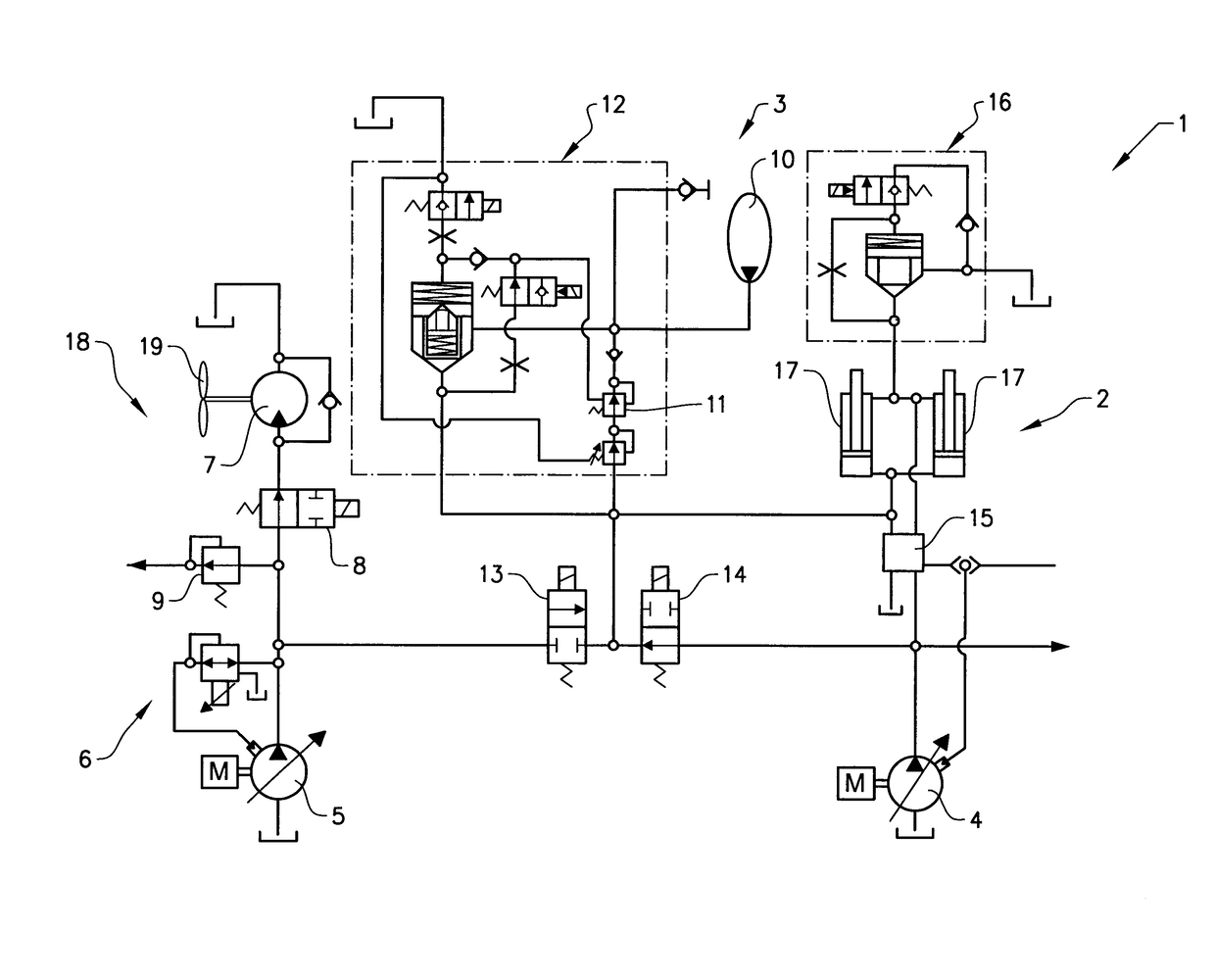
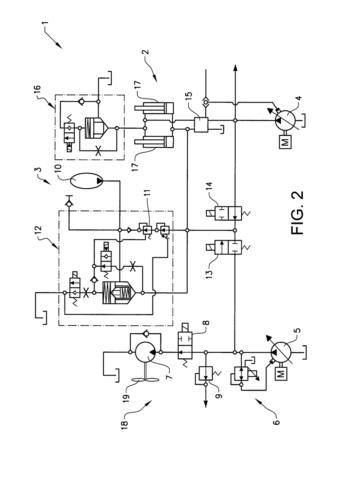
[0025]In an advantageous development of the inventive method, the first hydraulic pump is connected to the accumulator and the second pump is disconnected from the accumulator when a temperature signal for the cooling fan is above a predefined level and / or when a brake pressure signal is below a predefined level. In this way, the accumulator can be charged also when the second hydraulic pump is fully occupied. The accumulator can thus be charged without having to wait for the second hydraulic pump to be available. This reduces the delay time for the activation of the boom suspension system.

Problems solved by technology

The boom suspension system can however not be used constantly.
If the two systems have different pressures, the boom will move some in an uncontrolled way.
It would be detrimental to connect the high pressure lift cylinders to an empty accumulator or to an accumulator having a much lower pressure.
One drawback with the current charging system is that energy is lost each time oil is drained from the accumulator to balance the pressure.
This in turn increases the fuel consumption of the vehicle.
The accumulator is often filled at maximum pump pressure which causes further pressure losses.
The charging to the required pressure will thus take shorter time.

Method used


Image

  • Arrangement for charging an accumulator
  • Arrangement for charging an accumulator
  • Arrangement for charging an accumulator

Examples


Embodiment Construction

[0031]The embodiments of the invention with further developments described in the following are to be regarded only as examples and are in no way to limit the scope of the protection provided by the claims.

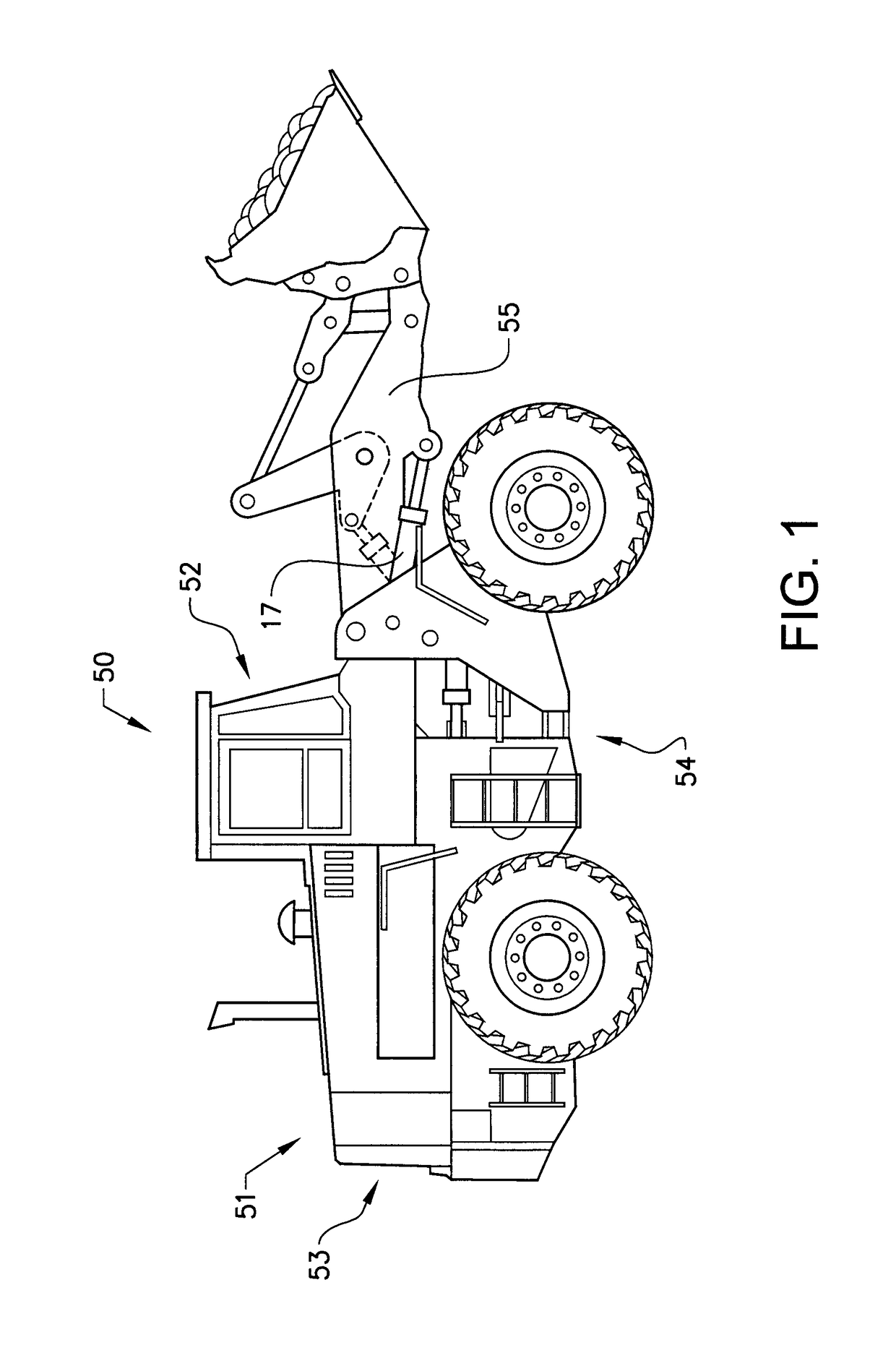
[0032]FIG. 1 is an illustration of a working machine 50 in the form of a wheel loader. The wheel loader comprises a bucket arranged on lift arms 55 for lifting and lowering the bucket and the bucket can further be tilted relative to the lift arms. The wheel loader 50 is provided with a hydraulic system 54 comprising at least one hydraulic machine (not shown in FIG. 1). The hydraulic machine or pump can be used for providing the hydraulic cylinders with hydraulic fluid, for example to lift and tilt the bucket. The hydraulic system also comprises an inventive arrangement for charging the accumulator used with the boom suspension system.

[0033]In the example embodiment illustrated in FIG. 1 the hydraulic system comprises two hydraulic lift cylinders 17 for the operation of the lift ar...


PUM


Abstract

An arrangement for charging an accumulator with hydraulic fluid is provided. The accumulator is used in a hydraulic boom suspension system for a lift arm of a vehicle and the arrangement includes a first hydraulic pump arranged to supply hydraulic fluid to a hydraulic cylinder system of the lift arm, and a second hydraulic pump arranged to supply hydraulic fluid to a second hydraulic system. The second hydraulic pump is further arranged to supply hydraulic fluid for charging the accumulator.

Description

BACKGROUND AND SUMMARY[0001]The present invention relates to an arrangement for charging an accumulator. The arrangement is suitable for use in for example working machines.[0002]Working machines, such as wheel loaders and excavators and other construction equipment are often equipped with a hydraulic oil pressure system that powers e.g. the boom operating system and the arm and bucket lifting system. The hydraulic system may be equipped with a suspension system in order to take up load variations and to relieve the system from sharp impulses. On wheel loaders, such a system is used to damp the boom and is referred to as a boom suspension system (BSS). The BSS system utilities a gas / oil accumulator connected to the lift cylinders to absorb shocks and smooth out rough roads. This in turn allows for faster cycle times and less spillage and will also increase the comfort of the operator. When the boom suspension system is activated, the accumulator is connected to the lift cylinder sys...

Claims


Application Information

Patent Timeline
Patent Type & Authority Patents(United States)
IPC IPC(8): E02F9/22F15B1/04F15B1/02
CPCF15B1/04E02F9/226E02F9/2207E02F9/2217E02F9/2292F15B1/021E02F9/2296F15B2211/8613F15B2211/20546F15B2211/20576F15B2211/625
Inventor VIGHOLM, BOEKVALL, ANDREASHEYBROEK, KIM
Owner VOLVO CONSTR EQUIP AB
Learn More