
Oxide film deposition method and oxide film deposition device

a technology of oxide film and deposition device, which is applied in the direction of oxygen/ozone/oxide/hydroxide, chemical equipment and processes, coatings, etc., can solve the problems of not being able to use alkyl compound in the atmosphere film formation process, practicably impossible to gasify alkyl compound, etc., to improve the efficiency of film formation, improve the speed of oxide film formation, and be prepared stably

Active Publication Date: 2018-07-10
TOSHIBA MITSUBISHI-ELECTRIC IND SYST CORP
View PDF38 Cites 2 Cited by
  • Summary
  • Abstract
  • Description
  • Claims
  • Application Information

AI Technical Summary

Benefits of technology

[0017]In the present invention, a raw material solution containing an alkyl compound is formed into a mist and then ejected to a substrate in the atmosphere. Then, an oxidizing agent that exerts an oxidizing effect on the alkyl compound is supplied to the mist of the raw material solution.
[0018]Accordingly, in the present invention, the mist of the raw material can be positively exposed to a sufficient amount of oxidizing agent in addition to the moisture, and the like, contained in the atmosphere. Therefore, in a case of forming an oxide film by using the mist method, formation of the oxide film can be surely achieved, the speed of formation of the oxide film (the efficiency of film formation) can be improved, and the oxide film having a desired performance can be stably prepared with a good reproductivity.
[0019]Additionally, in the present invention, in addition to the moisture, and the like, contained in the atmosphere, the oxidizing agent can be positively and sufficiently supplied to the mist of the raw material. Therefore, even when, for example, the amount of moisture contained in the atmosphere is changed due to an influence of the temperature and humidity, the oxide film can be formed on the upper surface of the substrate with almost no influence given from the change in the moisture (that is, normal formation of the oxide film is always achieved in the atmosphere).

Problems solved by technology

In the chemical vapor deposition process, however, the film has to be formed under vacuum, which requires a large vacuum vessel in addition to a vacuum pump, and the like.
Moreover, the chemical vapor deposition process involves a problem that a substrate with a large area is not adoptable as a substrate on which the film is to be formed from the viewpoint of costs, and the like.
Therefore, it is practically impossible that the alkyl compound is gasified and used in a film formation process which is performed in the atmosphere (gasifying a solution containing an alkyl compound causes liberation of an alkyl compound gas and a gas resulting from a solvent from each other, so that the alkyl compound gas is directly in contact with the atmosphere to cause ignition or the like).
Furthermore, the technique of the Patent Document 1 does not employ the method in which diethyl zinc or the like is gasified and a substrate arranged in the atmosphere is exposed to the gasified diethyl zinc or the like, but employs a method in which a raw material solution containing diethyl zinc is sprayed to a substrate.

Method used


Image

  • Oxide film deposition method and oxide film deposition device
  • Oxide film deposition method and oxide film deposition device
  • Oxide film deposition method and oxide film deposition device

Examples


embodiment

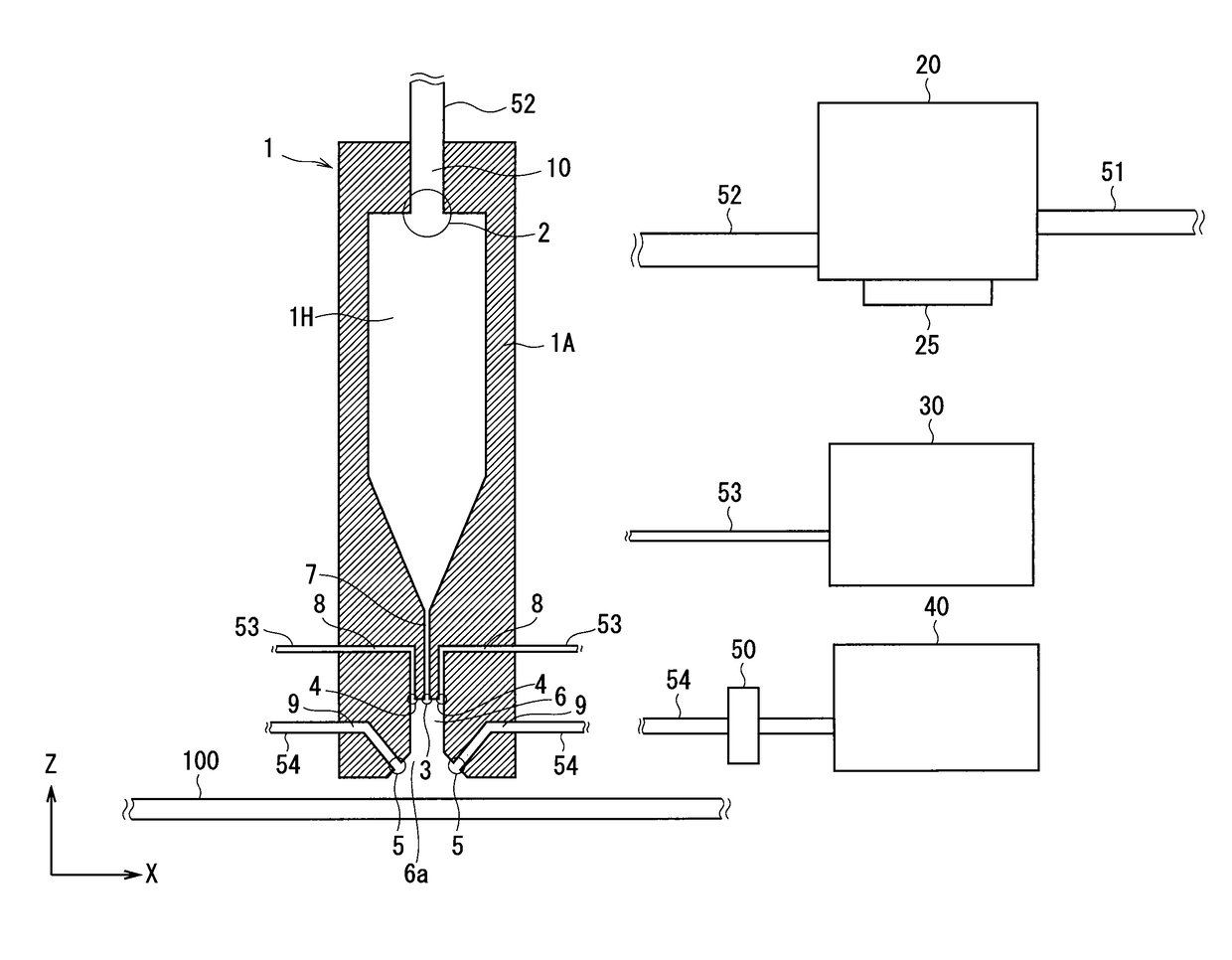
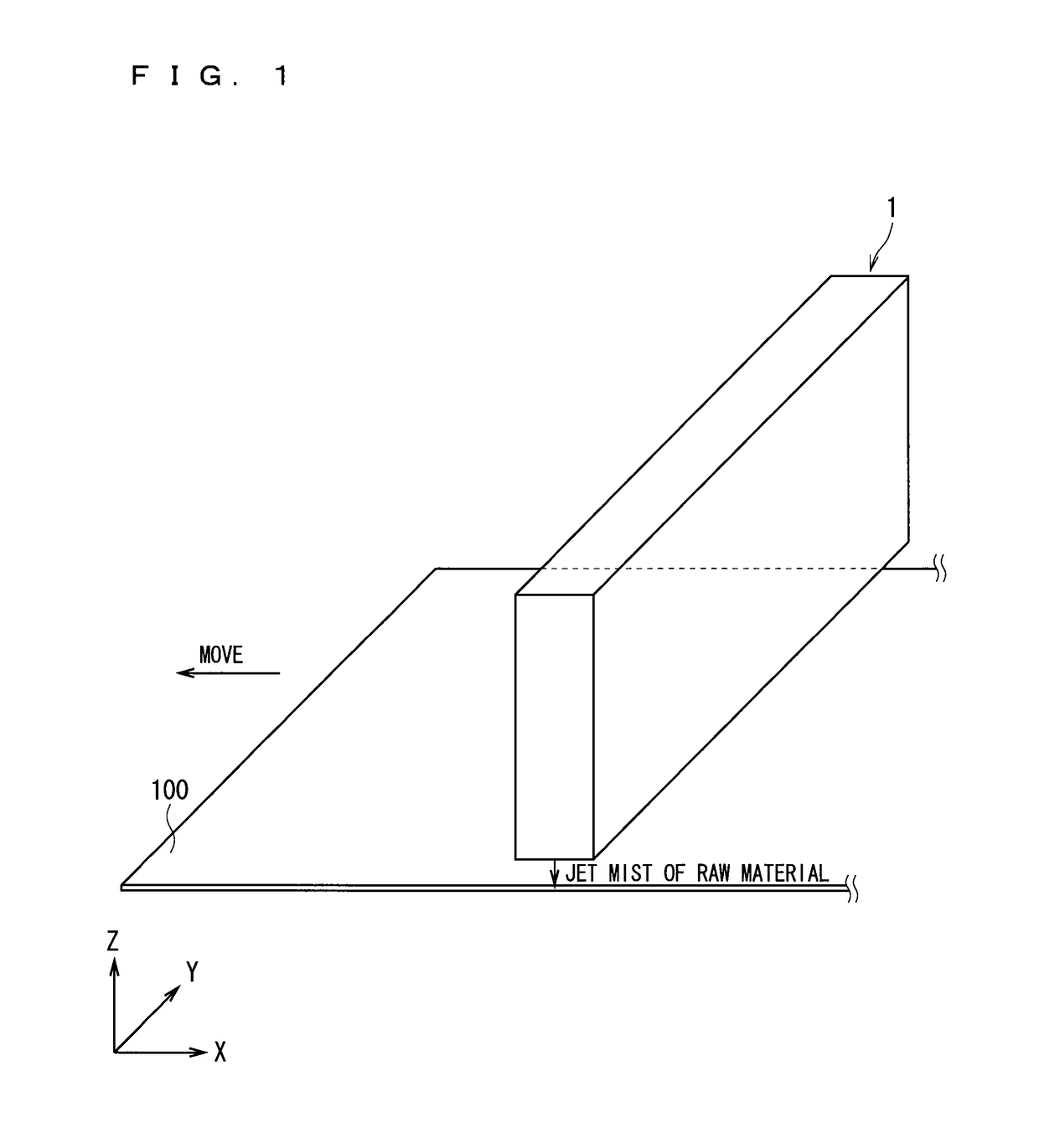
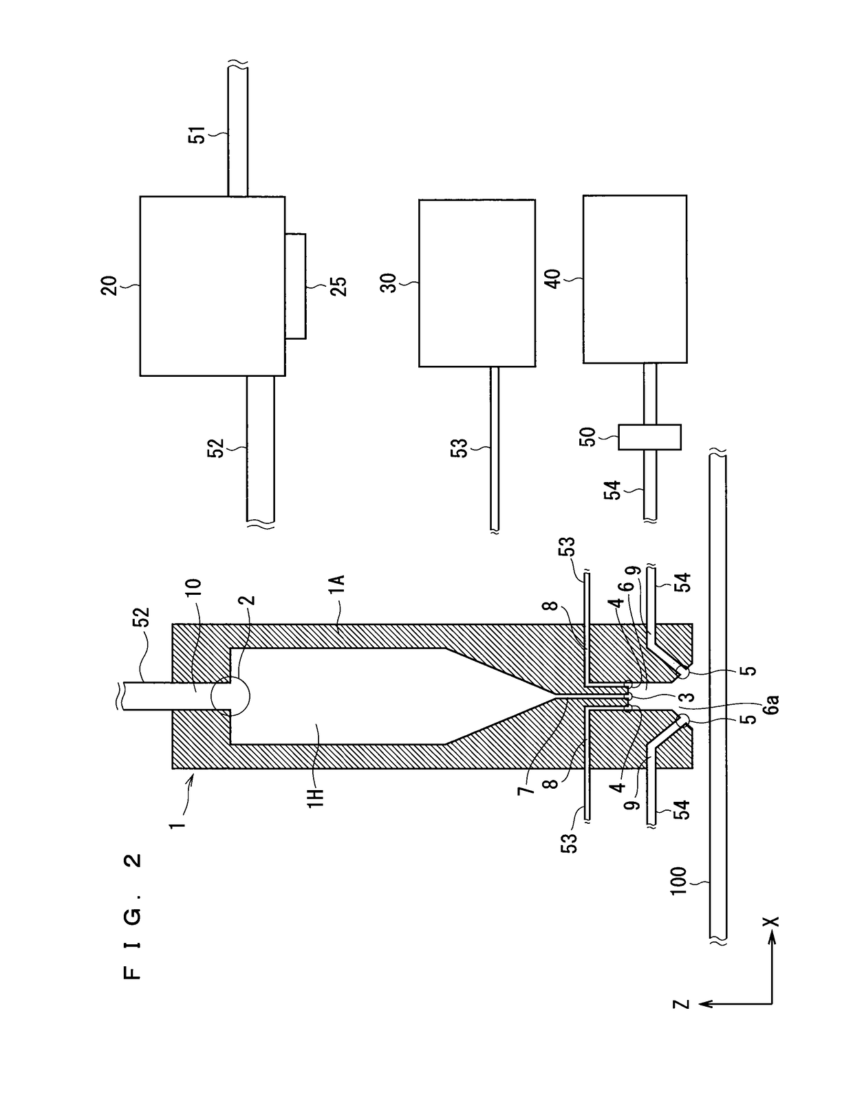
[0036]FIG. 1 is a perspective view showing a configuration of an external appearance of a mist jet nozzle 1 included in an apparatus for forming an oxide film according to an embodiment. FIG. 1 shows coordinate axes X-Y-Z, too. FIG. 2 is a cross-sectional view showing an outline configuration of the whole of the apparatus for forming an oxide film. FIG. 2 shows a cross-section of the configuration shown in FIG. 1 as seen along the Y direction.

[0037]For simplification of the drawing, FIG. 1 does not show chambers 20, 30, 40, pipes 51, 52, 53, 54, an ultrasonic atomizer 25, and a supply adjustment unit 50, which are shown in FIG. 2. In FIG. 1, for simplification of the drawing, an internal configuration of the mist jet nozzle 1 is not illustrated, either. FIG. 2 shows an X-Z coordinate system, too. In FIG. 2, for illustrating the internal configuration of the mist jet nozzle 1, the mist jet nozzle 1 is illustrated with an enlarged size relative to the sizes of the chambers 20, 30, and...


PUM

PropertyMeasurementUnit
sizeaaaaaaaaaa
diameteraaaaaaaaaa
droplet diameteraaaaaaaaaa

Abstract

The present invention provides a method for forming an oxide film by which normal formation of an oxide film is always achieved without receiving an influence of a change in the atmosphere, a metal oxide film having a low resistance can be formed, and a high efficiency of film formation is obtained. In the present invention, a raw material solution containing an alkyl compound is formed into a mist and ejected to a substrate (100) in the atmosphere. Additionally, an oxidizing agent that exerts an oxidizing effect on the alkyl compound is supplied to the mist of the raw material solution. Through the above-described processes, an oxide film is formed on the substrate in the present invention.

Description

CROSS-REFERENCE TO RELATED APPLICATIONS[0001]This application is a National Stage of PCT / JP2011 / 070783 filed on Sep. 13, 2011.BACKGROUND OF THE INVENTIONTechnical Field[0002]The present invention relates to a method for forming an oxide film and an apparatus for forming an oxide film.Background Art[0003]An oxide film is a functional thin film that exerts various kinds of performance in accordance with a constituent element thereof (conductive properties, insulating properties, piezoelectric properties, magnetic properties, dielectric properties, superconductive properties), and, because of the diversity of its physical properties, applied to the fields of many electronic devices. For example, a zinc oxide thin film, which serves as a transparent conductive film having conductive properties, is used in a solar cell, an LED (Light Emitting Diode), a touch panel, or the like.[0004]An example of a method for manufacturing the zinc oxide thin film is a chemical vapor deposition (CVD) pro...

Claims


Application Information

Patent Timeline
Patent Type & Authority Patents(United States)
IPC IPC(8): C23C16/40B05D3/04C23C16/18C23C16/448C23C16/452B05C5/00
CPCB05D3/0453B05C5/00B05D3/0466C23C16/452C23C16/40C23C16/4486C23C16/18C01B13/34C23C16/44
Inventor ORITA, HIROYUKISHIRAHATA, TAKAHIROHIRAMATSU, TAKAHIRO
Owner TOSHIBA MITSUBISHI-ELECTRIC IND SYST CORP
Learn More