Method and arrangement for the relative position detection of stations by means of radio location

a technology of relative position detection and radio location, which is applied in the direction of direction finders, instruments, measurement devices, etc., can solve the problems of high cost, complex technology of radio modules in mobile units and base stations,

Active Publication Date: 2018-06-26
SIEMENS AG
View PDF18 Cites 1 Cited by
  • Summary
  • Abstract
  • Description
  • Claims
  • Application Information

AI Technical Summary

Benefits of technology

[0010]It is an object of the present invention to provide an improved method and arrangement for detecting the relative position of stations through radio location.

Problems solved by technology

However, the radio modules in the mobile unit and in the base stations are technically complex and hence expensive in this case.

Method used


Image

  • Method and arrangement for the relative position detection of stations by means of radio location
  • Method and arrangement for the relative position detection of stations by means of radio location
  • Method and arrangement for the relative position detection of stations by means of radio location

Examples


Embodiment Construction

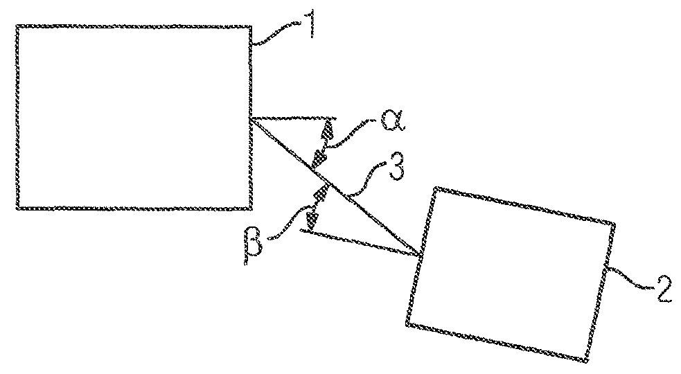
[0032]FIG. 1 shows an exemplary embodiment of angle and interval measurement between two stations 1, 2 by means of radio location. It shows the position of two stations 1, 2 in relation to one another. The position angles α, β are indicated relative to a line of sight 3. If the first station has precisely one antenna, it is possible to determine the position angle β. If the first station has two or more antennas, it is possible to determine both position angles α, β.

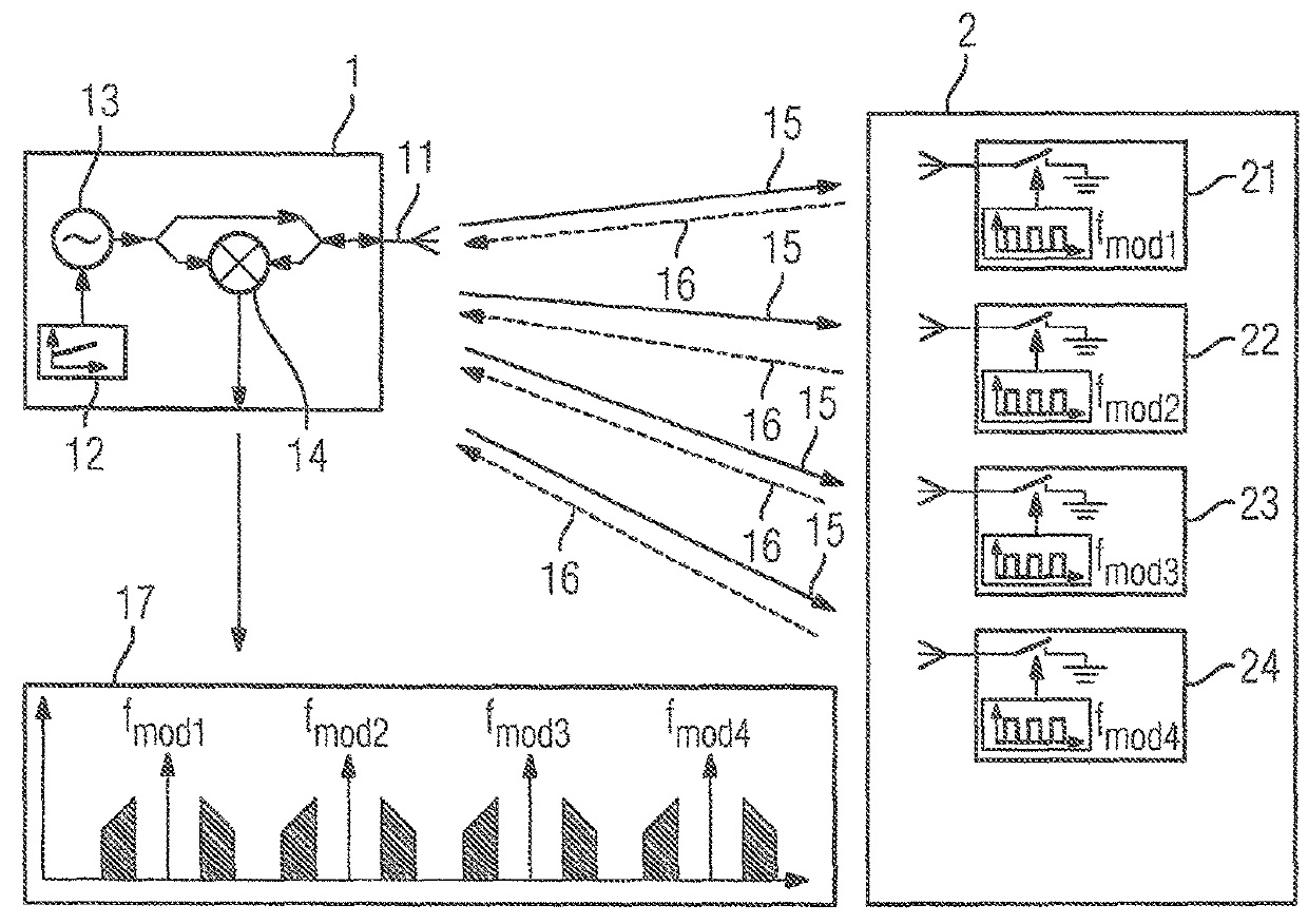
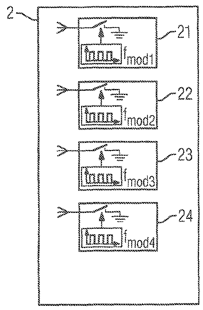
[0033]FIG. 2 shows an exemplary embodiment of an arrangement for detecting the relative position of the stations 1, 2 through radio location. It shows a first station 1 having an antenna 11. In addition, a switch 12, an AC supply 13 and an evaluation unit 14 are shown for the first station 1 in symbol form, so that the first station 1 is a full, active transmission and reception station with its own power supply 13 and complex hardware equipment. In addition, a second station 2 is shown. The second station 2 has four bas...


PUM


Abstract

A system and method for determining the relative position of stations through radio location is proposed. In one aspect, a station is configured as an apparatus having at least one antenna. At least one first station has at least one first antenna, and at least one second station has at least two base-modulated antennas. The first station sends at least one locating signal via the first antenna. The second station reflects the locating signal as a first modulated reflected locating signal via a first base-modulated antenna and as a second modulated reflected locating signal via a second base-modulated antenna. The first station receives the modulated reflected locating signals via the antenna. The phase relationships of the received modulated reflected locating signals are used to ascertain at least one position angle for the relative position between the first station and the second station.

Description

CROSS-REFERENCE TO RELATED APPLICATIONS[0001]This is a U.S. national stage of application No. PCT / EP2013 / 063879, filed on Jul. 2, 103, which claims priority to the German Application No. DE 102012211890.8 filed Jul. 6, 2012, the content of both incorporated herein by reference.BACKGROUND OF THE INVENTION[0002]1. Field of the Invention[0003]The present application generally relates to a method and an arrangement for ascertaining the relative position of at least two stations by means of radio location.[0004]2. Related Art[0005]Local radio location systems for determining the position of one or more mobile radio modules are widely used today. Methods using radio waves are distinguished by properties such as robustness, accuracy and insensitivity toward interfering and environmental influences.[0006]One example of the application of such a radio location system is the automotive industry. With an eye toward the increasing importance of electromobility, electric vehicles are expected to...

Claims


Application Information

Patent Timeline
Patent Type & Authority Patents(United States)
IPC IPC(8): G01S13/75G01S13/02G01S13/82G01S5/02G01S3/48
CPCG01S13/75G01S3/48G01S13/82G01S13/02G01S13/758G01S5/0284
Inventor HUTTNER, JORGZIROFF, ANDREAS
Owner SIEMENS AG
Why Eureka
Try Eureka