
Depth of field processing

a technology of depth of field and processing system, which is applied in the field of depth of field processing system, can solve the problems of not being able to achieve a sufficiently large aperture for compact digital cameras and digital cameras integrated into smartphones and tablets, affecting the accuracy of blur applied in that region, so as to increase the intensity of applied blur and increase the fall-off rate of applied blur

Active Publication Date: 2018-06-19
FOODIM LTD
View PDF18 Cites 0 Cited by
  • Summary
  • Abstract
  • Description
  • Claims
  • Application Information

AI Technical Summary

Benefits of technology

[0017]The processor may be configured to increase the fall-off rate of the applied blur as the angle between the direction of capture and the predefined axis increases.

Problems solved by technology

Compact digital cameras and digital cameras integrated into smartphones and tablets are, however, not typically equipped with a lens system which is capable of achieving a sufficiently large aperture to produce a shallow depth of field.
This approach suffers from several problems.
If only a limited number of focus regions are defined, each region can itself span a range of focal depths meaning that any blur applied to that region will not be accurate for all of the features in the region.
If a large number of focus regions are defined, the processing requirements would be very substantial—although in practice the limiting factor is likely to be the resolution of focus information from the autofocus system, which will normally only provide focus information for a limited number of zones (e.g. no more than 16).
In order to provide a reasonable depth of field effect, such conventional systems will therefore suffer from high latency, substantial image processing requirements and high power consumption.
Operating such systems using focus information determined over only a limited number of frames will lead to poor performance and an unrealistic depth of field effect.
This approach provides an unrealistic depth of field since the same amount of blur is applied to all regions outside the selected region, irrespective of their true focal depth.

Method used


Image

  • Depth of field processing
  • Depth of field processing
  • Depth of field processing

Examples


Embodiment Construction

[0043]The following description is presented by way of example to enable a person skilled in the art to make and use the invention. The present invention is not limited to the embodiments described herein and various modifications to the disclosed embodiments will be apparent to those skilled in the art.

[0044]There is a need for a fast and low power technique for realistically simulating depth of field for a wide range of scenes at a digital camera which is not equipped with a lens system enabling a physical depth of field to be produced.

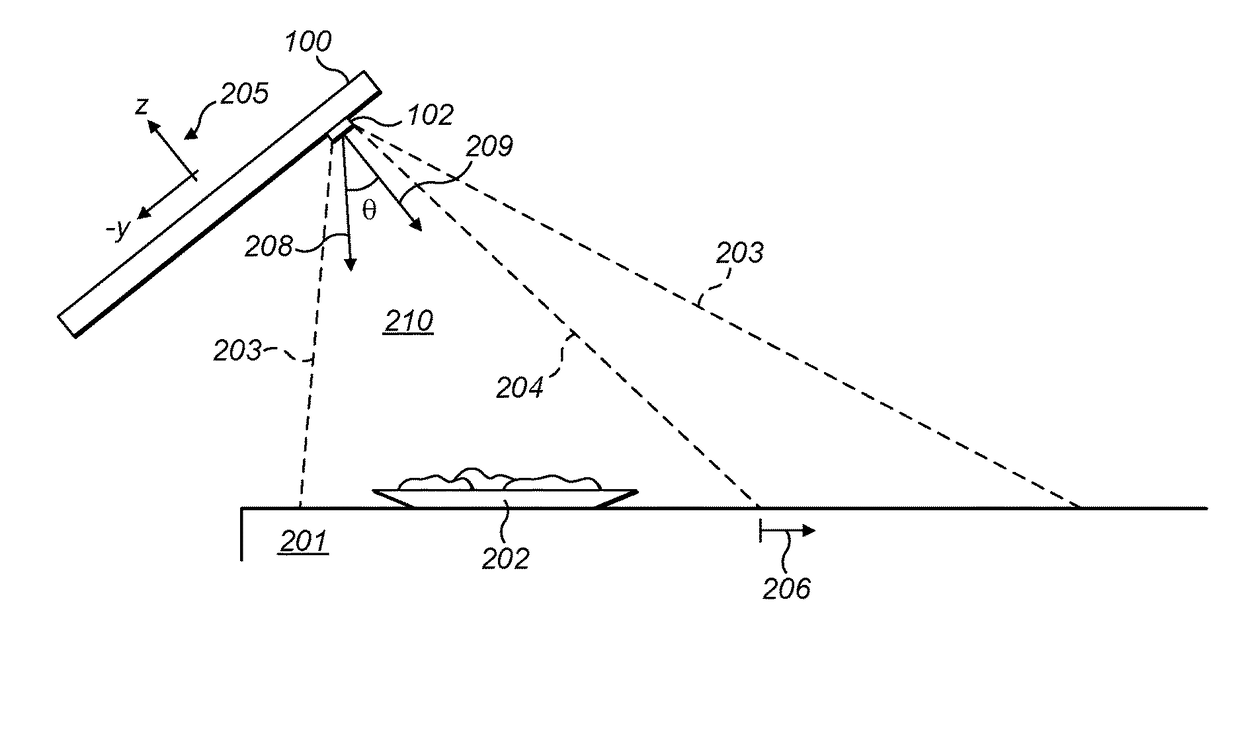
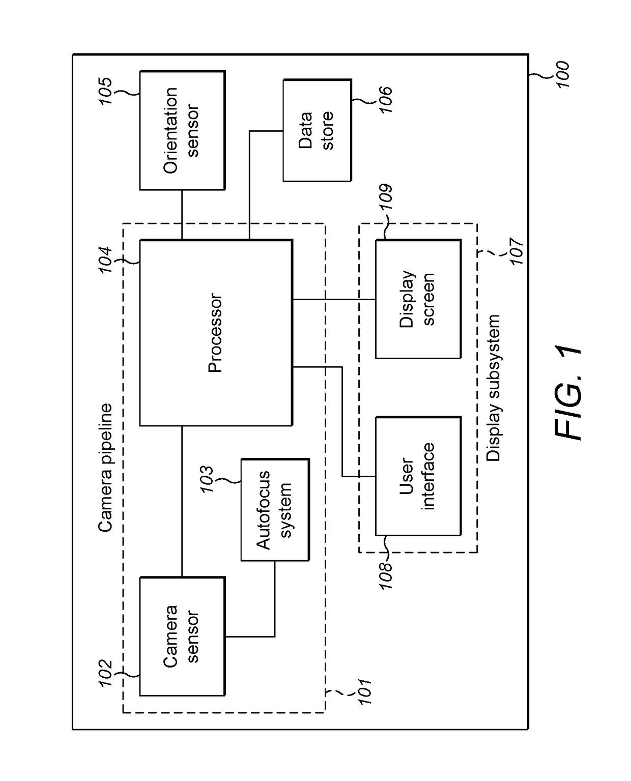
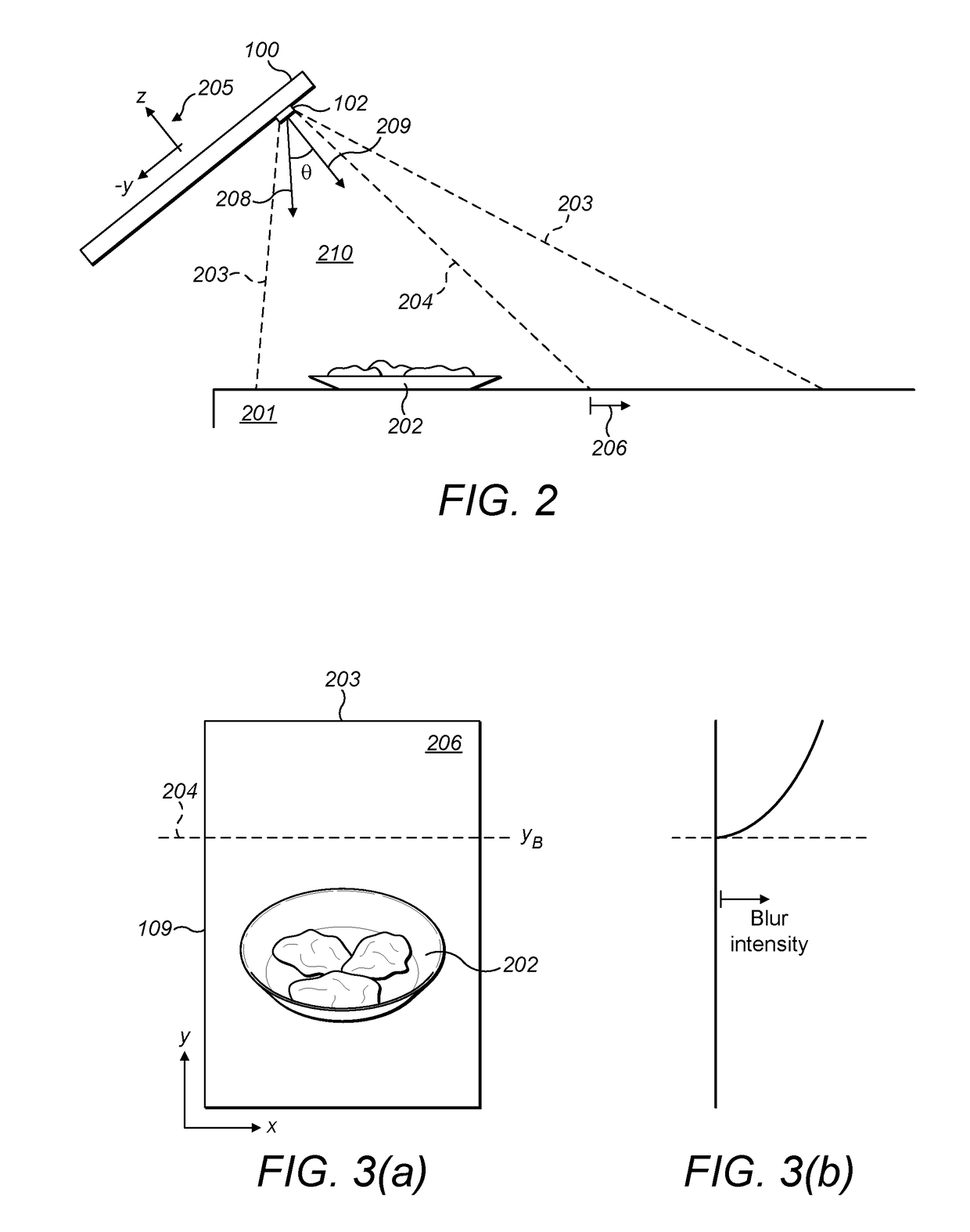
[0045]FIG. 1 shows an image processing device configured to simulate a depth of field effect in a captured image. The image processing device 100 comprises a camera sensor 102, a processor 104 and an orientation sensor 105. The camera sensor and processor may belong to a camera pipeline 101 which could pre-process captured images prior to the application of a blur effect, e.g. by performing automatic control of contrast, white balance, exposure etc....


PUM


Abstract

An image processing device for simulating depth of field in a captured image, the image processing device comprising: a camera sensor configured to capture an image; an orientation sensor configured to determine an orientation of the device from which the direction of capture of the image by the camera sensor is derivable; and a processor configured to apply blur to a first area of the captured image in dependence on the orientation of the device.

Description

BACKGROUND OF THE INVENTION[0001]This invention relates to an image processing system for simulating depth of field in a captured image.[0002]A shallow depth of field can be produced in an image by using a camera lens having a large aperture (typically expressed as a small f-number). Compact digital cameras and digital cameras integrated into smartphones and tablets are, however, not typically equipped with a lens system which is capable of achieving a sufficiently large aperture to produce a shallow depth of field.[0003]Various techniques are described in the prior art for simulating a depth of field effect in a digital camera which is not equipped with a lens system capable of a large enough aperture size to physically produce a shallow depth of field. These techniques rely on digitally post-processing captured images to add a depth of field effect.[0004]For example, U.S. Pat. No. 9,025,874 uses information generated by an autofocus system to form a measure of the relative focal d...

Claims


Application Information

Patent Timeline
Patent Type & Authority Patents(United States)
IPC IPC(8): G06K9/00H04N5/232G06T5/00
CPCH04N5/23212G06T5/002G06T2200/24G06T2207/10028G06T2207/20012G06T2207/30244
Inventor KADRI, ROMIINGLE, JIMKIDD, NEVILLE
Owner FOODIM LTD
Learn More