Reducing cost of cellular backhaul

A data transmission and wireless transmission technology, applied in network topology, electrical components, selection devices, etc., can solve problems such as wireless line system limitations, and achieve the effect of reducing costs

Inactive Publication Date: 2007-07-11
VANU INC
View PDF0 Cites 3 Cited by
  • Summary
  • Abstract
  • Description
  • Claims
  • Application Information

AI Technical Summary

Problems solved by technology

Wireless backhaul has the advantage of lower cost compared to leased T1 lines, but wireless systems are often limited by range and terrain

Method used


Image

  • Reducing cost of cellular backhaul
  • Reducing cost of cellular backhaul
  • Reducing cost of cellular backhaul

Examples


Embodiment Construction

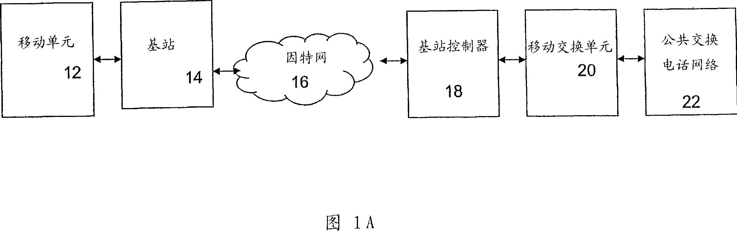
[0033] Referring to FIG. 1A , system 10 includes mobile unit 12 , base station 14 . The base stations are connected to the Internet 14 close to the backbone, and the cellular traffic is routed to the core network of the cellular service provider by means of lightweight QoS mechanisms on site. The QoS mechanism provides the required service level for the system 10, so that the system does not rely on the existence of excessive bandwidth to provide the required service level.

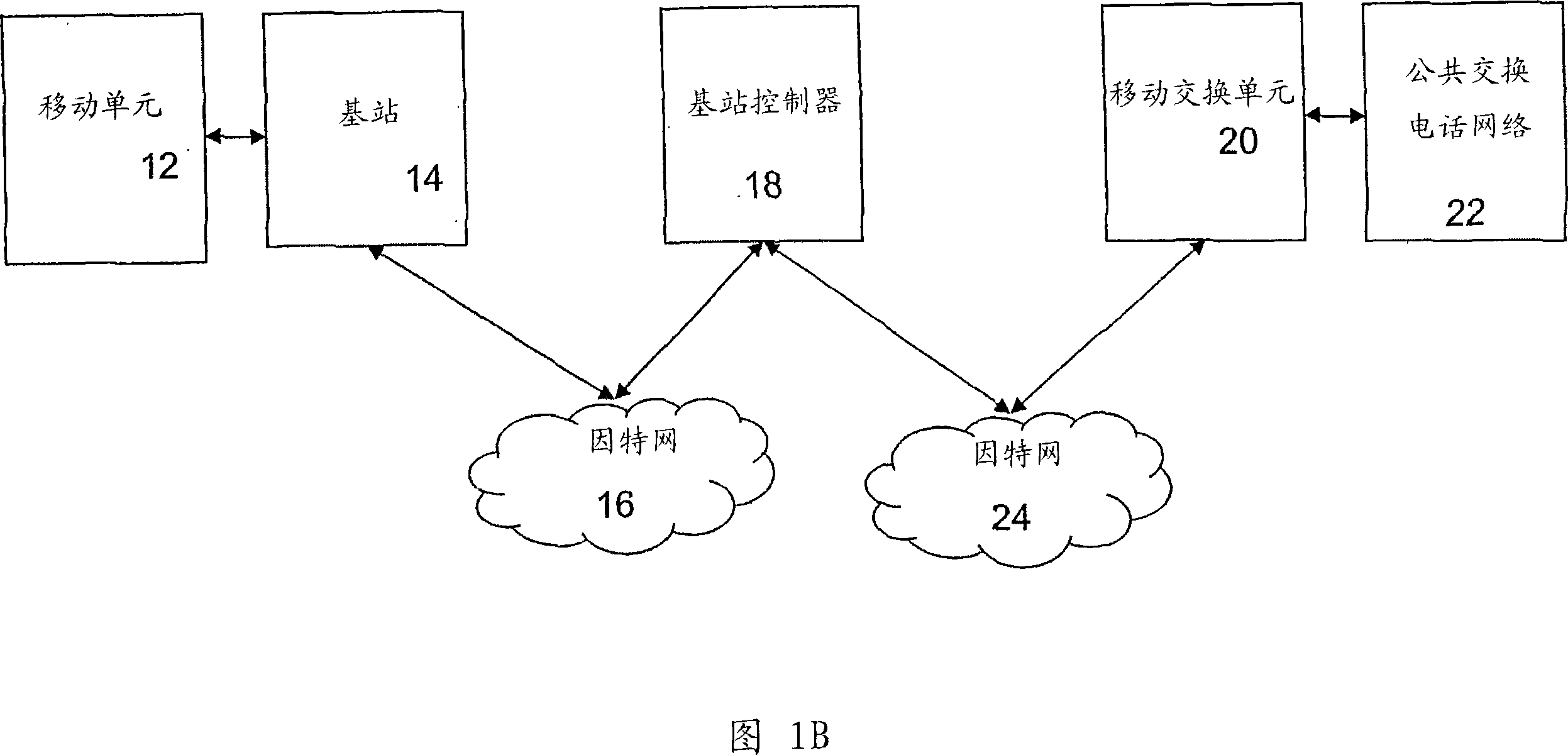
[0034] More particularly, system 10 includes a mobile unit 12 that transmits wireless signal transmissions to a base station 14 . Base station 14 routes the transmission to base station controller 18 over network 16 (eg, the public network). Base station controller 18 then routes the call to mobile switching unit 20 and mobile switching unit 20 routes the call to public switched telephone network 22 . In some embodiments, the signal traverses a second network (eg, the Internet 24 ) deployed between the ...


PUM


Abstract

Methods and systems for reducing the cost of cellular backhaul are disclosed. The methods and systems include using the public Internet (138) to backhaul cellular traffic given the wide availability and relatively low cost of Internet connections compared with dedicated T1 lines. Re-distribution of switching functionality between a base station (136) and a base station controller (140) is achieved by moving some of the switching functionality from the base station controller to the base station.

Description

[0001] This application claims priority to US Provisional Application No. 60 / 578,266, entitled "Reducing the Cost of Cellular Backhaul," filed June 9, 2004, the contents of which are incorporated herein by reference. technical field [0002] The following description refers to the radio system Background technique [0003] In today's cellular systems, voice, data and signaling traffic must be backhauled from the cell tower site to the central office where the mobile switching center is located. Typically, backhaul refers to passing data to the core network between, for example, a base station and a base station controller. In some cases, backhauling can include sending network data on "off-the-record" routes (including delivering it farther than its destination) in order to deliver the data more quickly or at a lower cost to its destination. Currently, most of this backhaul occurs on dedicated T1 lines. There are also some wireless backhaul modes mainly for small range ni...

Claims


Application Information

Patent Timeline
Patent Type & Authority Applications(China)
IPC IPC(8): H04Q7/20H04W88/08H04W92/12
CPCH04W92/12H04W84/042H04W88/08
Inventor 杰弗里·斯坦海德瓦努·博斯
Owner VANU INC
Why Eureka
Try Eureka