Zoom lens and imaging apparatus

一种变焦镜头、像侧的技术,应用在放映装置、洗印装置、透镜等方向,能够解决焦点移动等问题,达到提高画质、对焦状态良好的效果

Active Publication Date: 2007-07-04
SONY DIGITAL PROD WUXI CO LTD
View PDF4 Cites 6 Cited by
  • Summary
  • Abstract
  • Description
  • Claims
  • Application Information

AI Technical Summary

Problems solved by technology

But there is a problem: when the entire last lens group is displaced in a direction perpendicular to the optical axis, the image plane will move due to the unavoidable positional movement in the direction of the optical axis, which will cause the focus to move

Method used


Image

  • Zoom lens and imaging apparatus
  • Zoom lens and imaging apparatus
  • Zoom lens and imaging apparatus

Examples


Embodiment Construction

[0097] 0030

[0098] The best mode for implementing the zoom lens and imaging device of the present invention will be described below with reference to the drawings.

[0099] 0031

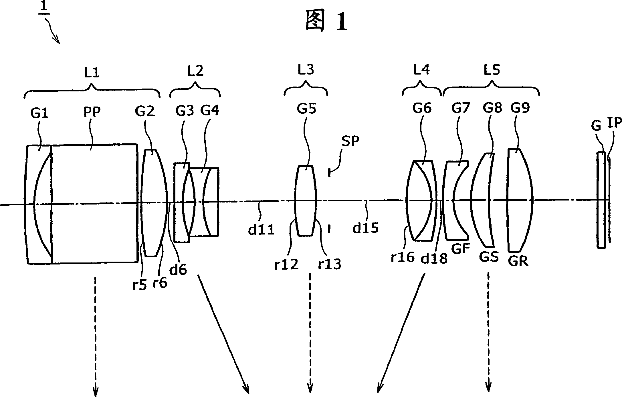
[0100] The zoom lens of the present invention is composed of a plurality of lens groups, and the magnification is changed by changing the distance between each lens group. The last lens group located on the image side includes a sub-lens group GS with a positive refractive index and is arranged adjacent to the image side. 1. The sub-lens group GR with a positive refractive index can make the above-mentioned sub-lens group GS displace along the direction perpendicular to the optical axis to correct the image movement, assuming that the lateral magnification of the above-mentioned sub-lens group GS is βs, the above-mentioned sub-lens group GR When the lateral magnification is βR, the following conditional expressions (1) and (2) are satisfied.

[0101] (1) βs<1,

[0102] (2) 0<βR<1.

[0103] The ...


PUM


Abstract

When positional displacement of the shift lens group in its optical axis occurs, an influence of out-of-focus caused by image surface movement is reduced to maintain high optical performance even in the handshake correction. The zoom lens (1) has lens groups, and the magnification of the lens is changed by varying the intervals between the lens groups. A final lens group (L5) located closest to the image side has a lens part group GS(G8) having positive refracting power and has a lens part group GR(G9) arranged next to the image side of the lens part group GS (G8) and having positive refracting power. Image blurring can be corrected by shifting the lens part group GS in the direction perpendicular to the optical axis. The zoom lens satisfies the conditional expressions of (1) sss < 1, and (2) 0 < ssR <1, where sss is the lateral magnification of the lens part group GS and ssR is the lateral magnification of the lens partial group GR.

Description

technical field [0001] 0001 [0002] The invention relates to a novel zoom lens and an imaging device. More specifically, it relates to a zoom lens capable of optically correcting image movement caused by hand movement during photography, and having a good miniaturization, and an imaging device including the zoom lens. Background technique [0003] 0002 [0004] Conventionally, various zoom lenses have been proposed that have a function of correcting image movement caused by hand movement that occurs during camera shooting. [0005] 0003 [0006] For example, the zoom lenses proposed in Patent Document 1 and Patent Document 2 include a first lens group with a positive refractive index, a second lens group with a negative refractive index, and a third lens group with a positive refractive index arranged in order from the object side. The lens group, the 4th lens group having a negative refractive index and the 5th lens group having a positive refractive index, at least th...

Claims


Application Information

Patent Timeline
Patent Type & Authority Applications(China)
IPC IPC(8): G02B15/16G03B5/00G02B13/18
CPCG02B5/04G02B15/173G02B27/646G02B15/145129G02B3/0087G02B15/145113G02B13/009G03B17/12H04N23/55
Inventor 畠山丈司黑田大介大竹基之岩泽嘉人
Owner SONY DIGITAL PROD WUXI CO LTD
Why Eureka
Try Eureka