Lamp having improved vibration damping

A lamp base and lamp holder technology, applied in the field of vehicle lamps, can solve problems such as broken working life, shortened lamp life, and unfavorable lamp life, and achieve the effects of good damping, increased life, and reduced possibility

Active Publication Date: 2007-07-04
LUMILEDS HLDG BV
View PDF1 Cites 3 Cited by
  • Summary
  • Abstract
  • Description
  • Claims
  • Application Information

AI Technical Summary

Problems solved by technology

[0004] All lamps of this type have the disadvantage that when used in a vehicle, because of their rigid structure, they transmit the vibrations occurring during operation of the vehicle undamped to the lamp cap, especia...

Method used


Image

  • Lamp having improved vibration damping
  • Lamp having improved vibration damping
  • Lamp having improved vibration damping

Examples


Embodiment Construction

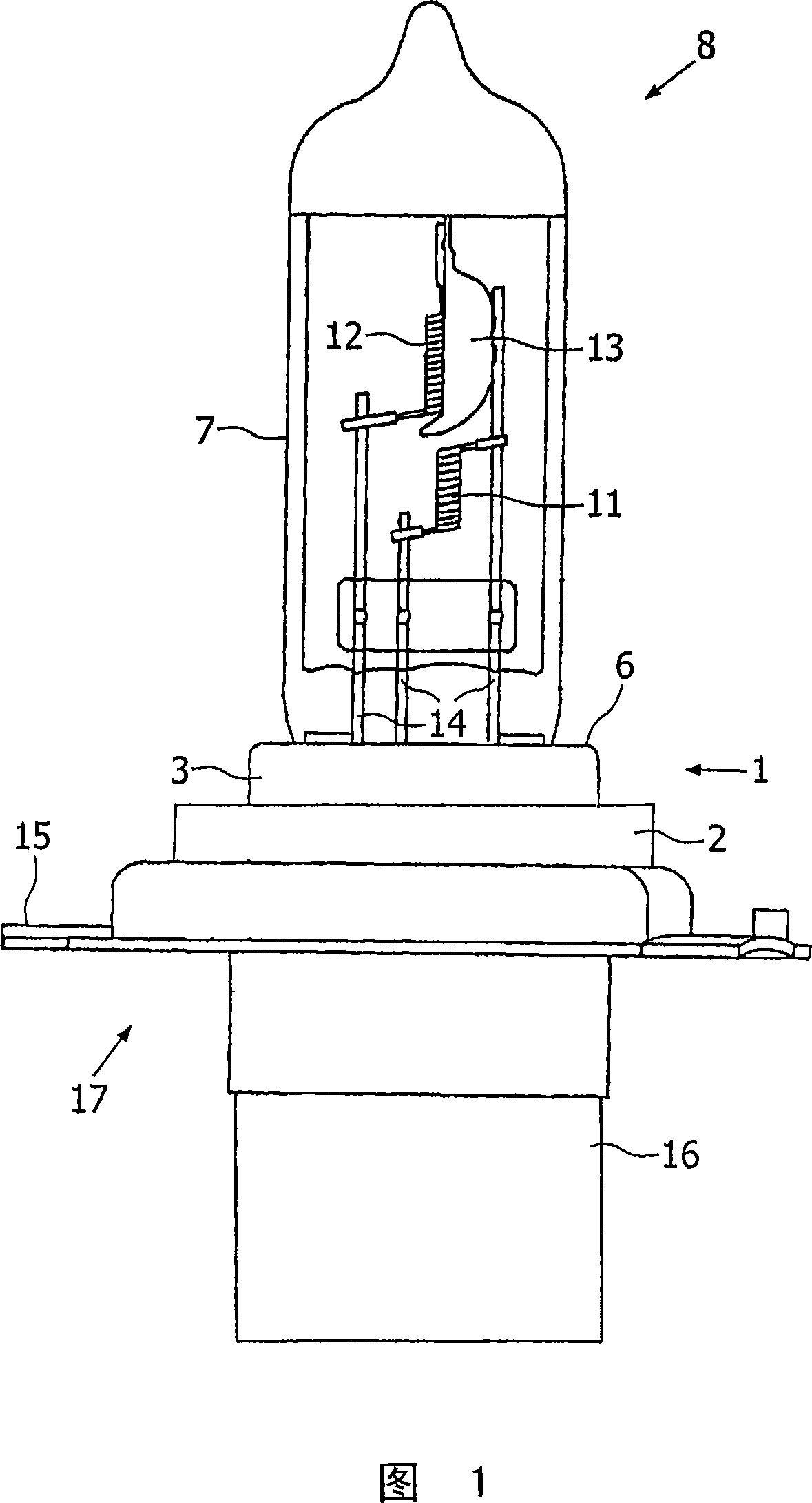
[0025] The exemplary embodiment of a lamp 8 according to the invention shown in FIG. 1 is a lamp 8 for a headlight (not shown in this case) of a motor vehicle.

[0026] The lamp 8 has a base 7 formed by a glass envelope in which two incandescent filaments 11 , 12 are located. The incandescent filaments 11 , 12 are supplied with current via fusible supply wires 14 which are fixed to corresponding terminal parts (not shown here) inside the socket 17 . One of the incandescent filaments 11 is provided with a dipped beam base 13 .

[0027] The positioning flange 15 and the terminal area 16 together form a socket 17 . The joint plate 1 is welded to a positioning flange 15 which is used to align the lamp 8 in the headlamp.

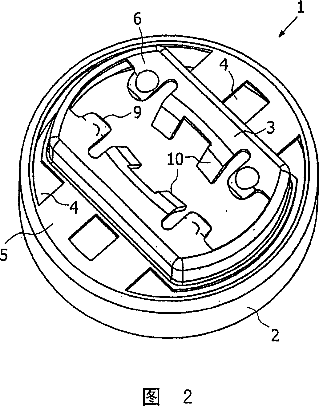
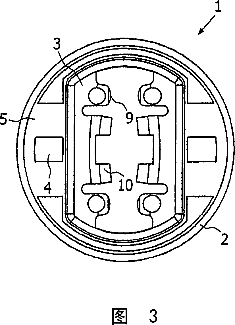
[0028] By means of the end of the cap adjacent to the cap 17, the cap 7 is held in place by clamping in the opening 9 in the receptacle 3 of the terminal plate 1, in this case being pressed against the support tab 10 of the wider side of the cap 7 Fix the lamp...


PUM


Abstract

The invention relates to a lamp (8), in particular a vehicle lamp, having a base (17), a burner (7) having a light-generating element (11, 12), and an adapter plate (1) having a connecting region (2) and a receiving portion (3), the connecting region (2) being connected to the base (17) and the receiving portion (3) to the burner (7). The adapter plate (1) has cutouts (4) between the connecting region (2) and the receiving portion (3) such that the connection region (2) is no longer rigid but has a certain flexibility.

Description

technical field [0001] The invention relates to a lamp, in particular for a vehicle, having a lamp base, a base with a light emitting element, and a terminal plate with a connection area connected to the base and a receptacle connected to the base. Background technique [0002] Known lamps of this type have a base in which a light-emitting element, such as one or more incandescent filaments, is formed in a glass envelope. In such lamps, the connection of the lamp base to the base is carried out, for example, by using a terminal plate made of metal, which is connected on the one hand to the base and on the other hand to the base. In order to allow the lamp cap to be electrically connected to the lamp holder, the lamp holder has conductor guides through which the supply lines protruding from the lamp cap extend to corresponding terminals arranged in the terminal area of ​​the lamp holder for contacting the lamp. [0003] Known from DE 19601396 is a glueless capped incandescen...

Claims


Application Information

Patent Timeline
IPC IPC(8): F21V15/04H01K1/46H01J5/60H01R33/975F21Y101/00
CPCH01K7/02H01K1/46H01R33/975H01K9/08H01J5/60
Inventor J·弗勒克西格S·雷耶A·特兰普勒P·罗森穆勒
Owner LUMILEDS HLDG BV
Why Eureka
Try Eureka