Light-guiding board, negative-light mould set and liquid-crystal display device

A technology for backlight modules and liquid crystal display panels, applied in optics, nonlinear optics, diffusing elements, etc., can solve the problems of complex frame structure design, and achieve the effect of speeding up the design and manufacturing process and simplifying the structure design.

Inactive Publication Date: 2007-06-20
INNOCOM TECH SHENZHEN +1
View PDF0 Cites 0 Cited by
  • Summary
  • Abstract
  • Description
  • Claims
  • Application Information

AI Technical Summary

Problems solved by technology

[0007] In order to solve the problem that the frame structure design of the backlight module of the liquid crystal display device in the prior art is complicated, it is necessary to provide a backlight module that can simplify the structural design of the backlight module using it.

Method used


Image

  • Light-guiding board, negative-light mould set and liquid-crystal display device
  • Light-guiding board, negative-light mould set and liquid-crystal display device
  • Light-guiding board, negative-light mould set and liquid-crystal display device

Examples


Embodiment Construction

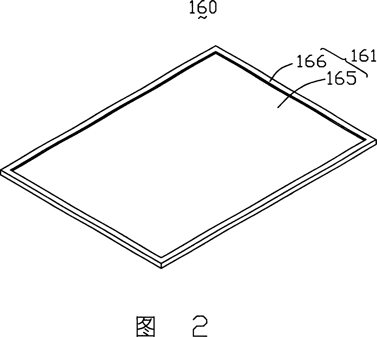
[0022] Please refer to FIG. 2 . FIG. 2 is a schematic structural diagram of the first embodiment of the light guide plate of the present invention. The light guide plate 160 is a flat plate with a light emitting surface 161 . The light emitting surface 161 is provided with a recessed portion 165 and a flange 166 surrounding the recessed portion 165 , and the recessed portion 165 can be produced together when manufacturing the light guide plate 160 by injection molding. The light-emitting surface of the light guide plate 160 is provided with a recessed portion 165 for accommodating the optical film used in the backlight module such as the diffusion film and the enhancement film, and the flange 166 can be used for tightly enclosing the optical film to achieve precise positioning of the optical film. purpose of the film.

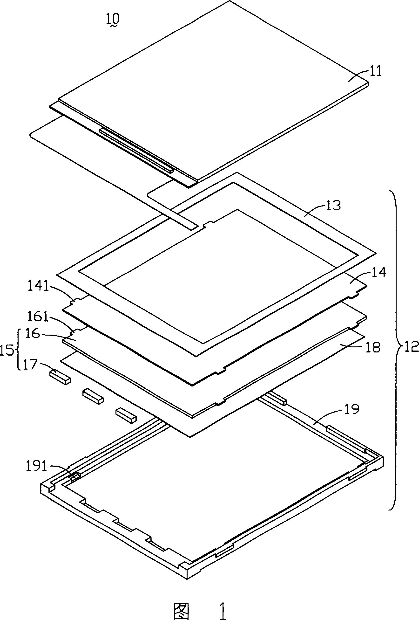
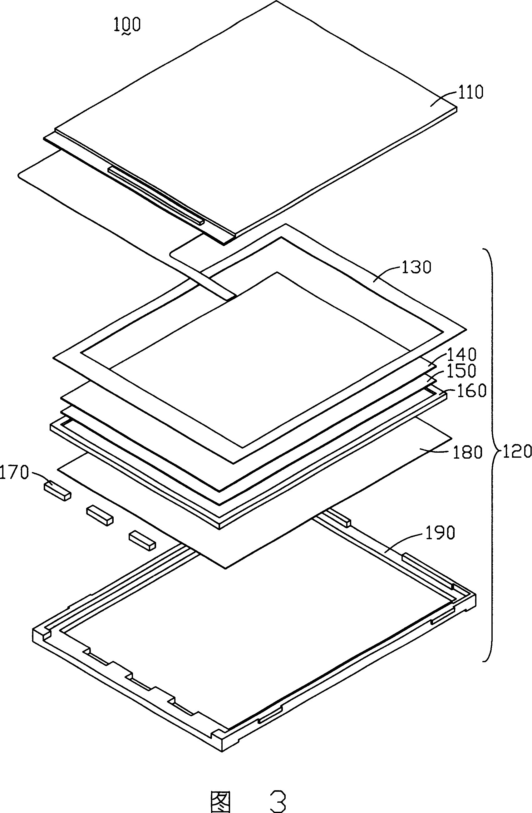
[0023] Please refer to FIG. 3 , which is a schematic structural diagram of a liquid crystal display device 100 using a light guide plate 160 . The liquid cry...


PUM


Abstract

A light guide plate is featured as arranging hollow unit being used to contain optical diaphragm on light outgoing surface. The frame design of back light module applying said light guide plate can be simplified much since optical diaphragm is directly contained in hollow unit of light outgoing surface on said light guide plate and it is not necessary to design additional structure to fix optical diaphragm on frame of back light module.

Description

【Technical field】 [0001] The invention provides a light guide plate, a backlight module and a liquid crystal display device using the light guide plate. 【Background technique】 [0002] Since the liquid crystal in the liquid crystal display panel does not emit light itself, in order to achieve the display effect, it is necessary to provide the liquid crystal display panel with a light source device, such as a backlight module, to realize the display function. [0003] The prior art backlight module includes a light source, a light guide plate and a frame. The frame is used to fix the various components of the backlight module. The light source is arranged relative to the light incident surface of the light guide plate. The light guide plate guides the transmission direction of the light beam emitted by the light source, and converts the light beam emitted by the line light source or point light source into a relatively uniform plane light for emission. A liquid crystal displ...

Claims


Application Information

Patent Timeline
IPC IPC(8): G02F1/1335G02B5/02
Inventor 彭祥恩
Owner INNOCOM TECH SHENZHEN
Why Eureka
Try Eureka