
Cooling apparatus

A kind of equipment, evaporative cooling technology, applied in the direction of water shower cooler, lighting and heating equipment, film technology, etc., can solve the problems of thermal efficiency and life impact of air cooler

Inactive Publication Date: 2007-06-13
SURREY AQUA TECH
View PDF1 Cites 2 Cited by
  • Summary
  • Abstract
  • Description
  • Claims
  • Application Information

AI Technical Summary

Problems solved by technology

Such deposits have an adverse effect on the thermal efficiency and life of the air cooler

Method used


Image

  • Cooling apparatus
  • Cooling apparatus

Examples


Embodiment Construction

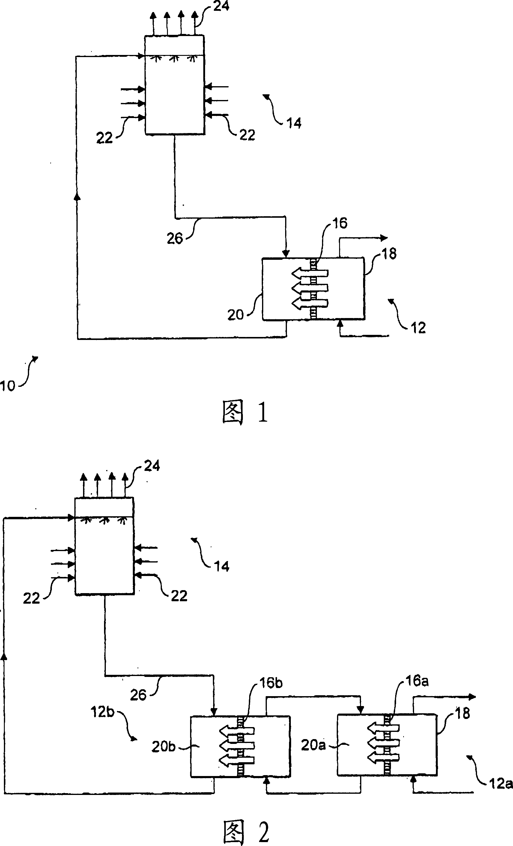
[0058] Referring to Fig. 1, there is provided an apparatus 10 for generating a flow of cold air.

[0059] The device 10 includes an enclosure 12 and an air cooler 14 . Housing 12 includes a selectively permeable membrane 16 for isolating seawater 18 and a solution 20 formed by dissolving a known amount of sodium chloride in water.

[0060]In use, seawater 18 is circulated through housing 12 on one side of membrane 16 while sodium chloride solution 20 is circulated through housing 12 on the opposite side of membrane 16 . The sodium chloride solution 20 in contact with the membrane 16 has a higher total dissolved salt (solute) concentration than the seawater 18 . Thus, water flows from the seawater side of the membrane 16 to the solution side of the membrane 16 by osmosis.

[0061] The flow of water through the membrane 16 dilutes the sodium chloride solution 20 . Diluted solution 20 is removed from housing 12 and directed into air cooler 14 . Air cooler 14 includes a porous...


PUM


Abstract

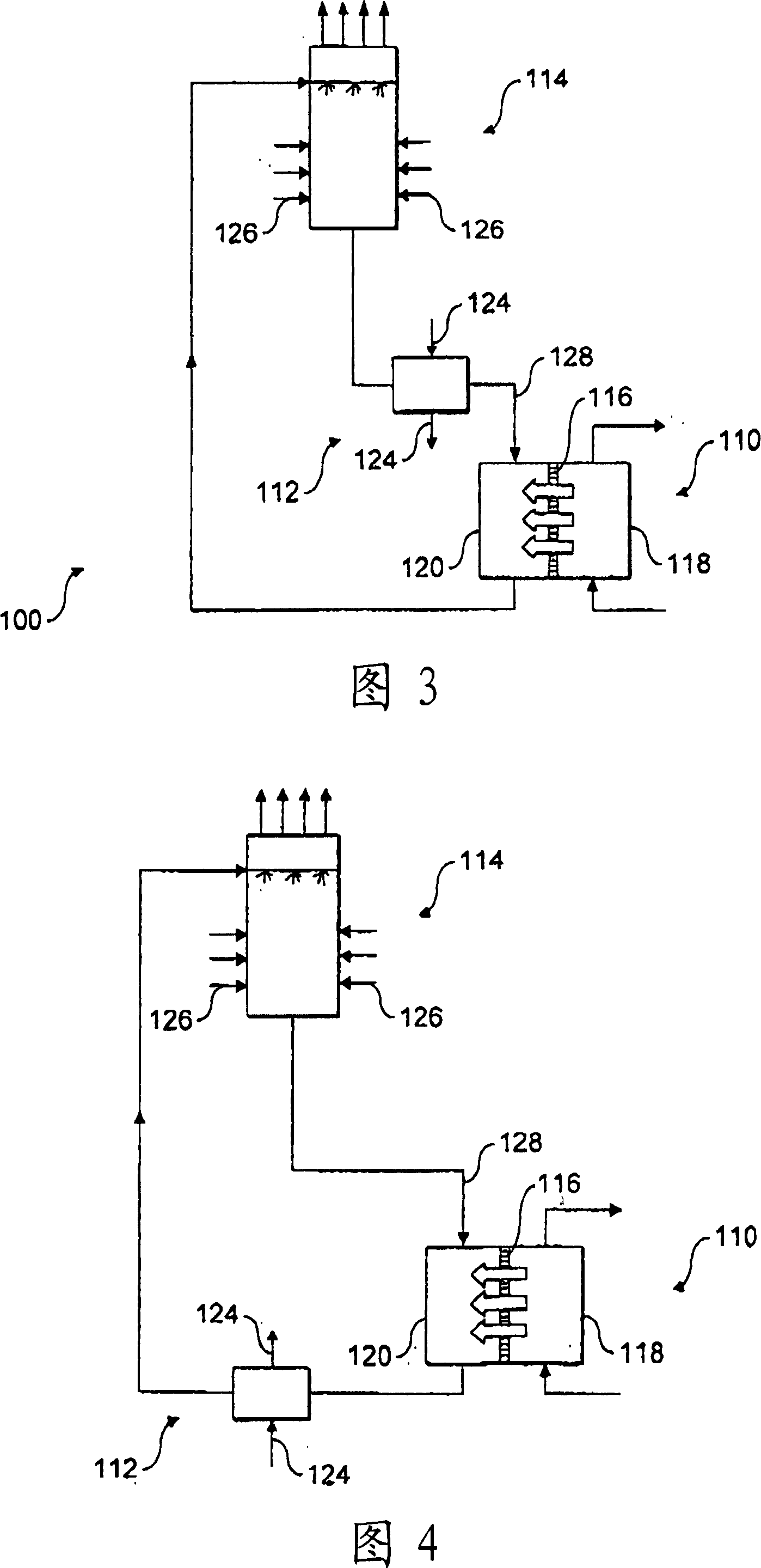
A process for introducing a solution into an evaporative cooling apparatus (14), said process comprising a) positioning a selectively permeable membrane (16) between a first solution (18) and a second solution (20) having a higher solute concentration than the first solution (18), such that the solvent from the first solution (18) flows across the selectively permeable membrane (16) to dilute the second solution (20), b) introducing the second solution into an evaporative cooling apparatus (14) in which solvent is removed from the second solution (20) by evaporation, and c) recycling the second solution (20) from step b) to step a) to draw solvent from the first solution (18).

Description

technical field [0001] The present invention relates to a method and apparatus for introducing a solution into a cooling device. In particular, but not limited to, the present invention relates to methods and apparatus for removing heat from a heat source. Background technique [0002] Heat exchangers are commonly used to remove excess heat from industrial processes. Typical heat exchangers include shell and tube heat exchangers having a section of tubing partially enclosed within a housing or housing. An industrial process fluid carrying excess heat is introduced into the piping while a coolant such as water flows through the housing through separate inlets and outlets. Water removes excess heat from the process fluid. In this way, the temperature of the water leaving the housing is higher than the temperature of the coolant entering the housing. The heated water stream is cooled in a cooling tower before it is recirculated back through the enclosure. This enables cont...

Claims


Application Information

Patent Timeline
Patent Type & Authority Applications(China)
IPC IPC(8): B01D61/00F28F25/00F28C1/00
CPCF28C2001/006B01D61/002F28C1/00F28F25/00Y02B30/70B01D61/0023
Inventor 阿卜杜勒萨拉姆·阿勒-马亚齐阿德尔·沙里夫
Owner SURREY AQUA TECH
Learn More