Router and communication system
A communication system and router technology, applied in the field of communication systems, can solve problems such as redundant paths, and achieve the effect of preventing redundant paths, inconsistency and address duplication.
- Summary
- Abstract
- Description
- Claims
- Application Information
AI Technical Summary
Problems solved by technology
Method used
Image

Examples
Embodiment 1
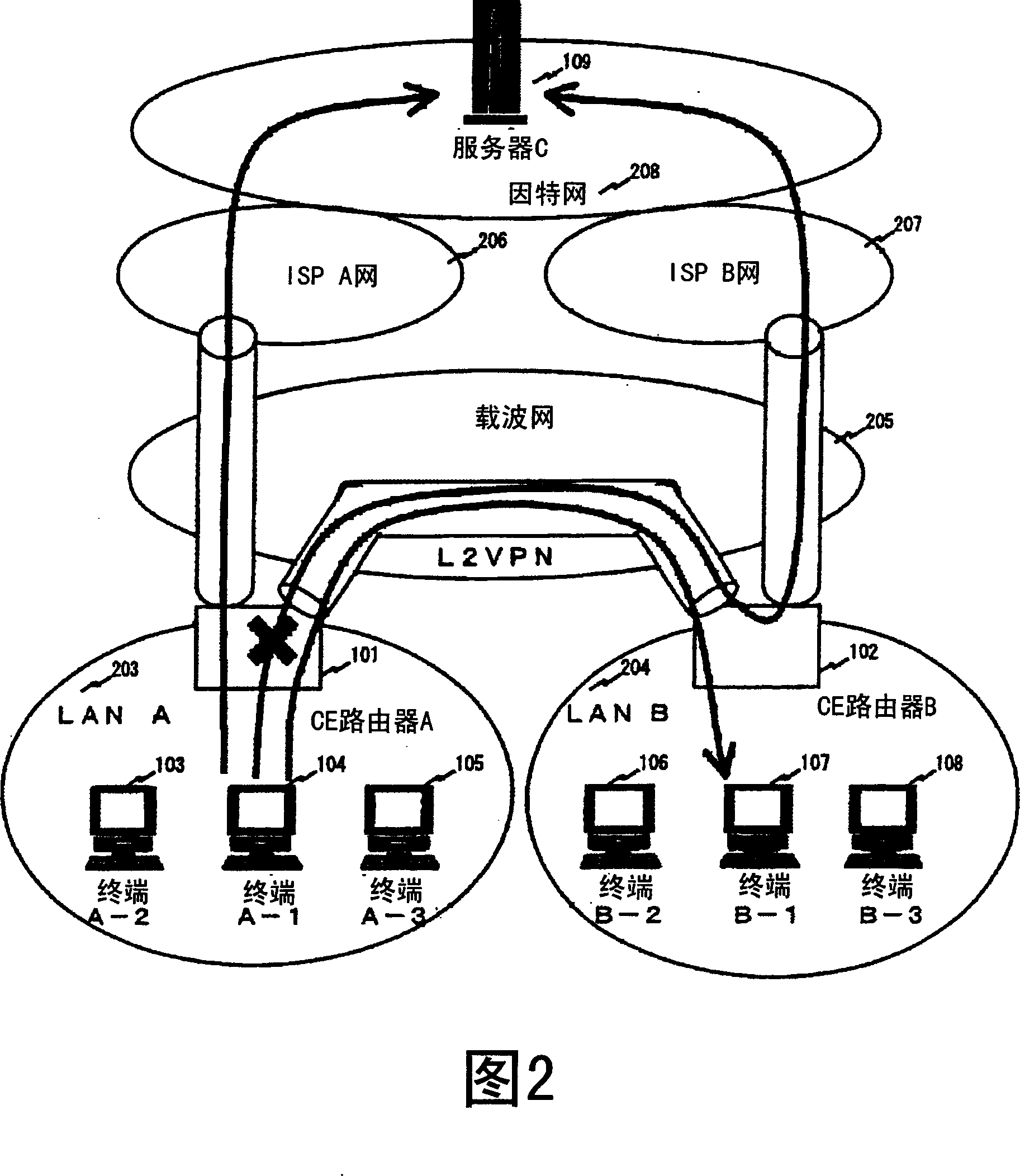
[0024] Figure 2 shows a communication system embodying the invention. The communication system includes CE router A101, CE router B102, LAN A203 to which CE router A belongs, LAN B204 to which CE router B belongs, carrier network 205, ISP A network 206, ISP B network 207, Internet 208, LAN Terminals A-1 104, A-2 103, and A-3 105 connected to A, terminals B-1 107, B-2 106, and B-3 108 connected to LAN B, and server C109 connected to the Internet. CE routers A, B (101, 102), carrier network 205, ISP networks A, B (206, 207), and Internet 208 are connected by using the Internet protocol.
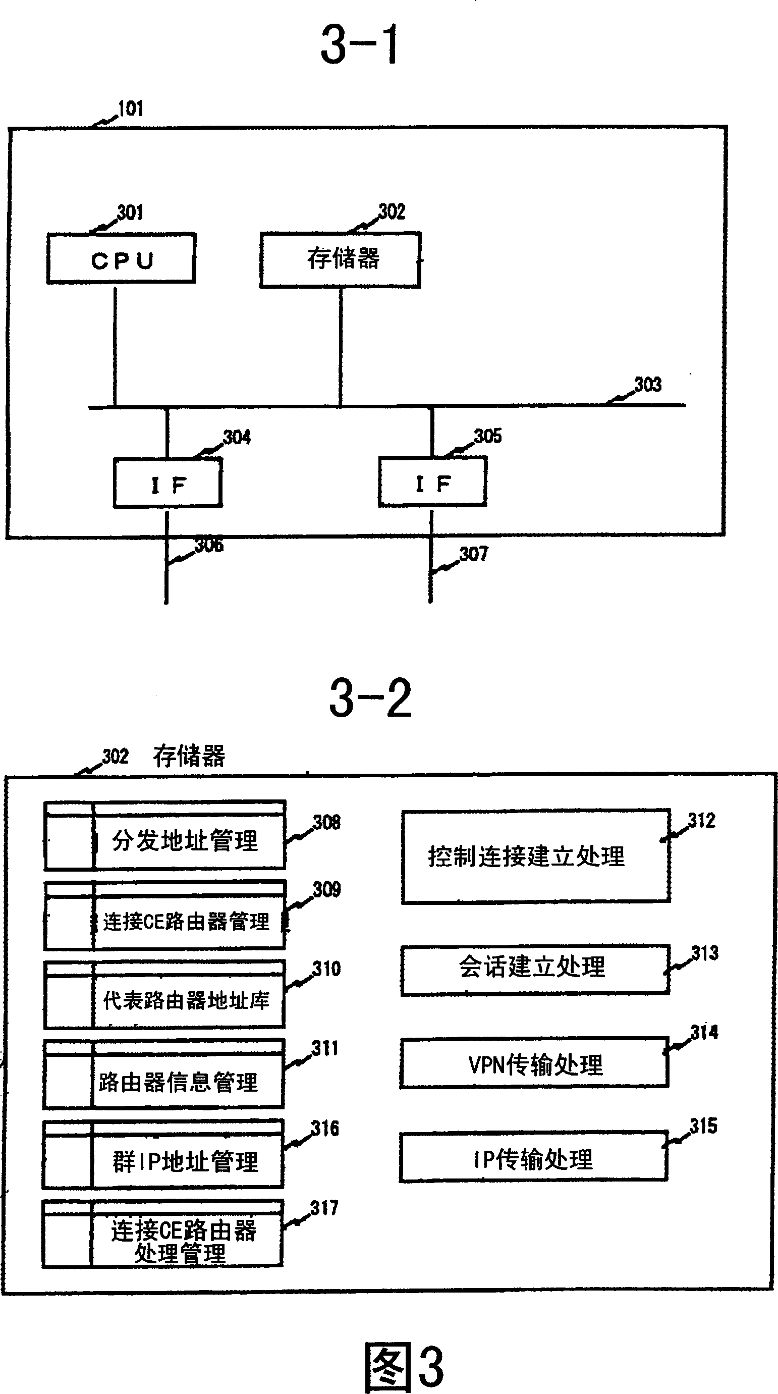
[0025] Figure 3-1 shows a configuration example of a CE router. The CE router A101 is composed of a CPU (Central Processing Unit) 301 , a memory 302 , and interface units 304 and 305 . CPU301 actually executes various application programs and OS (Operating System). The memory 302 stores programs used for execution by the CPU 301 and various application programs. CPU 301 and memory 302 are c...
Embodiment 2
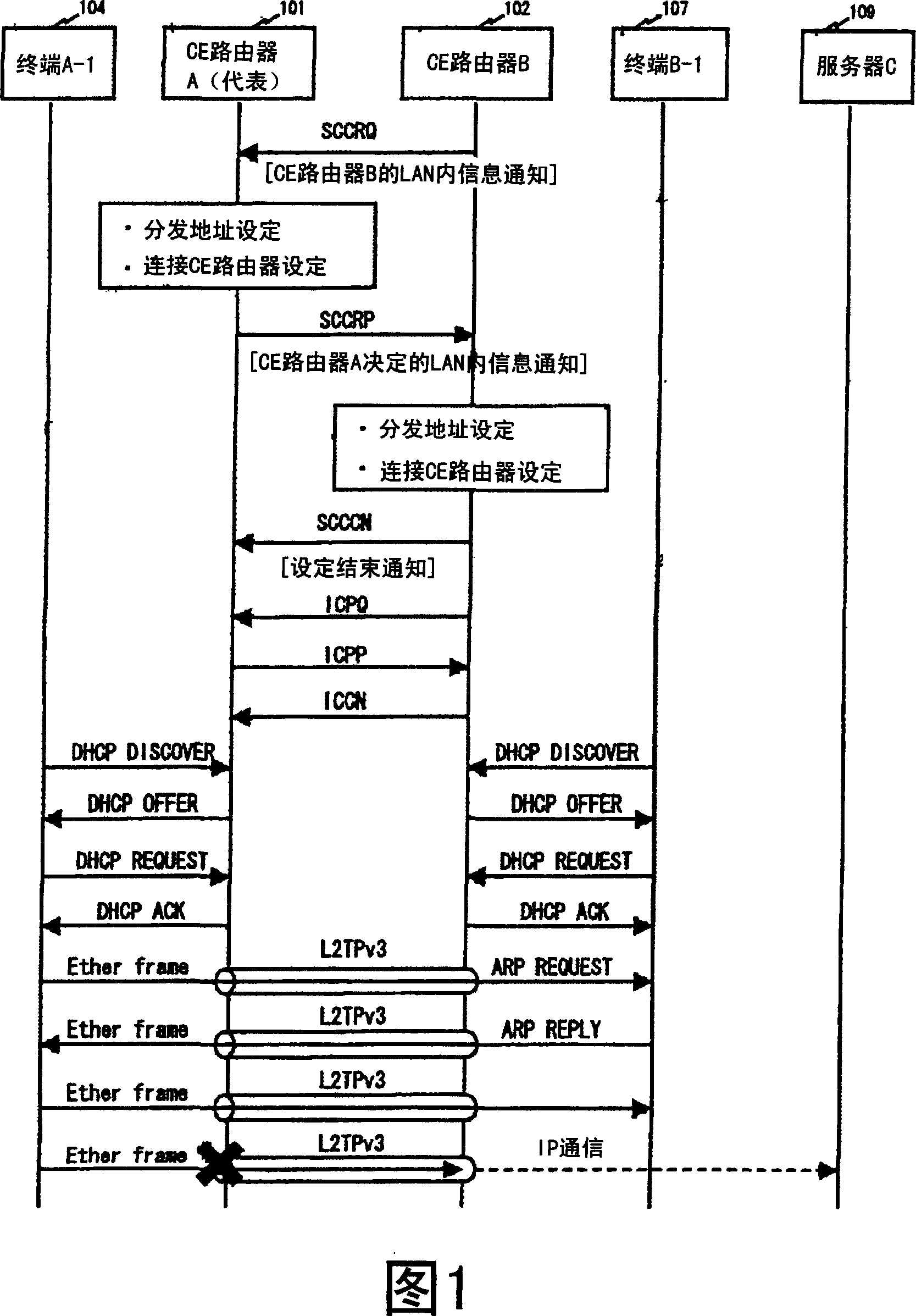
[0065] In Embodiment 2, an example in which the representative CE router prompts and controls the establishment of the connection will be described. FIG. 11 shows the procedure in which CE router A (representative) 101 prompts counterpart CE router B 102 to establish a control connection. The communication system implementing the invention and the setting conditions of various tables are the same as those in the first embodiment.
[0066] Figure 8-2 shows the flow of the connection control establishment process 312 on behalf of the CE router. Figure 9-2 shows the flow of the control connection establishment process other than the representative CE router.
[0067] The CE router A101 creates an AVP to notify the other CE router of the establishment of the control connection (step 814). In addition to the normal AVP at the time of controlling connection establishment, a router type AVP is created. Assign the created AVP to the SCCRQ message, and send the SCCRQ to CE router B ...
Embodiment 3
[0072] In Embodiment 3, a VPN is established between CE routers A101 and B102, and only CE router B102 is connected to the ISP. The terminal A-1 104 in LAN A 203 can communicate with the terminal B-1 107 in LAN B, and an example of cutting off the communication between the terminal A-1 104 and the server C 109 will be described. In addition, communication is possible from the terminal B-1 107 to the server C109.
[0073] Figure 12 shows a communication system embodying the present invention. The communication system includes: CE routers A101, B102, LAN A203 to which CE router A belongs, LAN B204 to which CE router B belongs, carrier network 205, ISP B207, Internet 208, terminal A-1 104 to which LAN A belongs, and LAN B to which LAN B belongs The terminal B-1 107 of , and the server C109 to which the Internet belongs. CE routers A101, B102, carrier network 205, ISP B network 207, and Internet 208 are connected by Internet protocol.
[0074] CE routers A101 and B102 perform t...
PUM
 Abstract
Description
Claims
Application Information
 - R&D
- Intellectual Property
- Life Sciences
- Materials
- Tech Scout
- Unparalleled Data Quality
- Higher Quality Content
- 60% Fewer Hallucinations
Browse by: Latest US Patents, China's latest patents, Technical Efficacy Thesaurus, Application Domain, Technology Topic, Popular Technical Reports.
© 2025 PatSnap. All rights reserved.Legal|Privacy policy|Modern Slavery Act Transparency Statement|Sitemap|About US| Contact US: help@patsnap.com