Plasma display device and its driving method

A plasma and display device technology, applied in the direction of identification devices, static indicators, instruments, etc., can solve the problems of wall charge loss, increased recombination ratio, and inability to display images, etc., and achieve the effect of preventing misdischarge and improving accuracy

Inactive Publication Date: 2007-06-06
LG ELECTRONICS(NANJING) PLASMA CO LTD
View PDF0 Cites 1 Cited by
  • Summary
  • Abstract
  • Description
  • Claims
  • Application Information

AI Technical Summary

Problems solved by technology

That is, in a high-temperature environment, the recombination ratio of wall charges and discharge space charges increases, resulting in the loss of wall charges, and the problem of misdischarge will become more serious.
Even, it will cause the discharge cell (cell) that should be turned on to be turned off, and the problem that the image cannot be displayed

Method used


Image

  • Plasma display device and its driving method
  • Plasma display device and its driving method
  • Plasma display device and its driving method

Examples


Embodiment Construction

[0094] In the following, preferred embodiments are given, and the plasma display device and its driving method in the present invention will be described in detail with reference to the accompanying drawings.

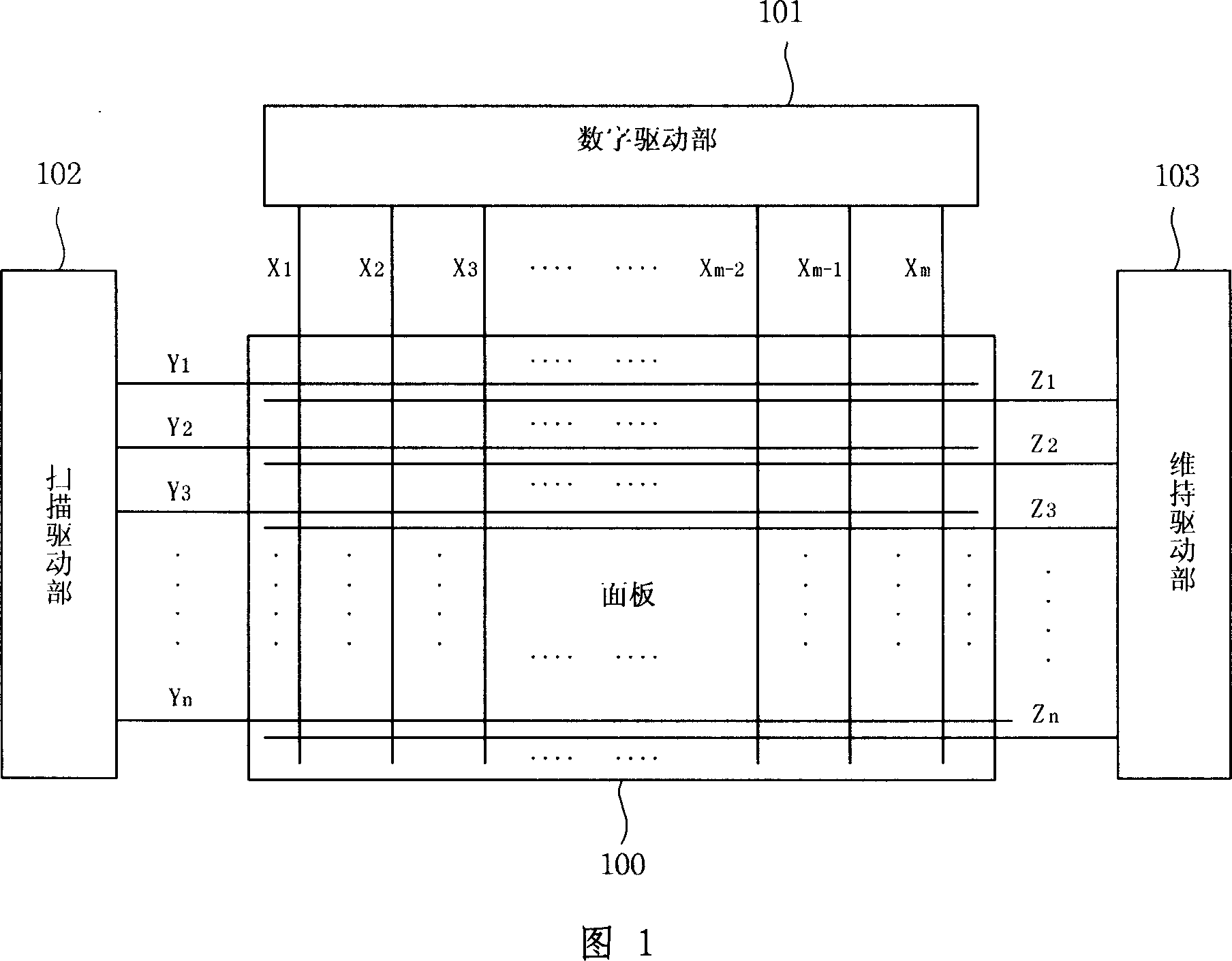
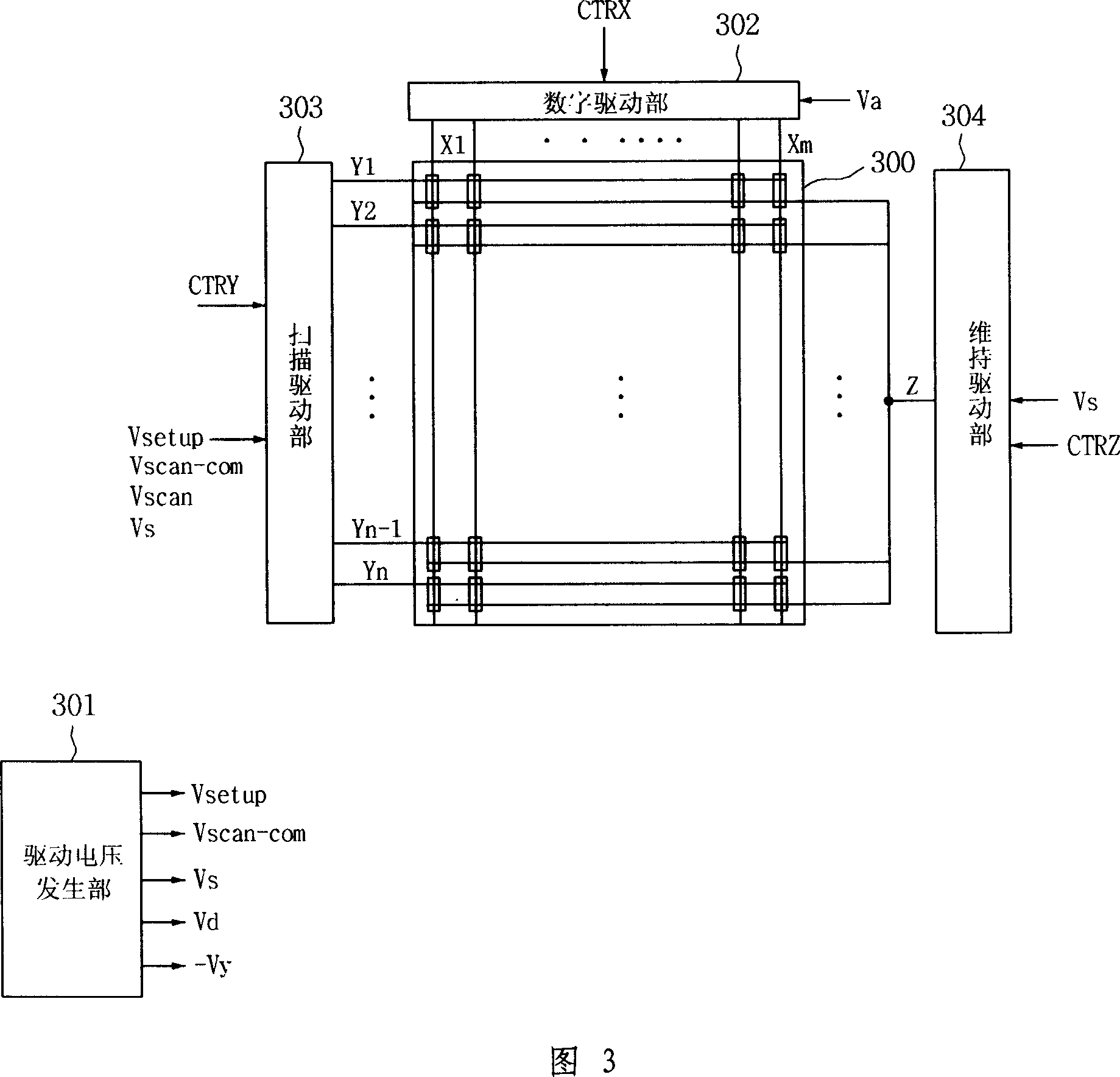
[0095] FIG. 3 is a schematic structural diagram of a plasma display device in the present invention.

[0096] As shown in FIG. 3 , the plasma display device of the present invention includes scan electrodes ( Y1 to Yn ) and sustain electrodes Z, and a plurality of digital electrodes ( X1 to Xm ) intersecting the scan electrodes and sustain electrodes Z.

[0097] In addition, it includes: during the reset period, the positioning period and the maintenance period, the plasma display panel 300 that negatively applies the driving pulse to the digital electrodes (X1 to Xm), the scan electrodes (Y1 to Yn) and the sustain electrode Z; The digital electrode (X1 to Xm) formed on 300 provides the digital driving part 302 of data; the scanning driving part 303 driving the scanning...


PUM


Abstract

The present invention relates to a plasma display device, and more specifically, relates to a plasma display device and a driving method thereof for adjusting a positive waveform voltage negatively applied to a sustain electrode, improving discharge accuracy, and improving jitter characteristics . As described above, the plasma display device in the present invention includes: a plasma display panel including sustain electrodes; a sustain drive unit that drives the sustain electrodes; and controls the sustain drive unit so that subfields (frame) During the falling edge period of sub-field) and the positioning period or during any one of the positioning periods, the positive polarity waveform voltage applied to the above-mentioned sustain electrode is changed from the first voltage level to the second voltage level with a certain gradient. The drive pulse control unit.

Description

technical field [0001] The present invention relates to a plasma display device, more specifically, to a plasma display device and a driving method thereof for adjusting a negative waveform voltage of a positive polarity applied to a sustain electrode. Background technique [0002] A general plasma display panel consists of a unit discharge cell (cell) formed by the interlayer formed between the front substrate and the back substrate, and each cell (cell) is filled with neon (Ne), helium (He), or neon and Main discharge gas such as mixed gas of helium (Ne+He) and a small amount of inert gas containing xenon. When the high-frequency voltage causes discharge, the inert gas generates vacuum ultraviolet rays (Vacuum Ultraviolet ray), which makes the phosphors formed between the interlayers emit light and display images. Such a plasma display panel has a light and thin structure, and is attracting attention as a next-generation display device. [0003] FIG. 1 is a schematic str...

Claims


Application Information

Patent Timeline
IPC IPC(8): G09G3/28G09G3/20H01J17/49G09F9/313G09G3/296
CPCG09G3/294G09G3/296
Inventor 文圣学
Owner LG ELECTRONICS(NANJING) PLASMA CO LTD
Why Eureka
Try Eureka