Vortex type compressor

A scroll compressor, compression chamber technology, applied in the direction of rotary piston machinery, rotary piston pump, mechanical equipment, etc., can solve the problems of further improvement of efficiency, breathing loss, compression loss, etc., to achieve the highest compression efficiency. Effect

Inactive Publication Date: 2007-05-30
HITACHI APPLIANCES INC
View PDF1 Cites 3 Cited by
  • Summary
  • Abstract
  • Description
  • Claims
  • Application Information

AI Technical Summary

Problems solved by technology

[0010] Needless to say, the above-mentioned prior art fully considers the generation of loss, but there is a problem with the further improvement of efficiency
[0011] That is, first, in the prior art described in Patent Document 1, when the pressure in the back pressure chamber rises, the fluid in the back pressure chamber is separated from the suction chamber by the pressure regulating valve, but in this case, the fluid after primary compression The high-pressure fluid expands back into the suction chamber, resulting in so-called re-expansion losses
[0012] Next, in the prior art described in Patent Document 2, the loss reduction is achieved by adjusting the back pressure, but as this method, a valve is provided on the cover plate of the orbiting scroll so that the back pressure chamber and the compression chamber are always in communication. In this case, during one rotation of the orbiting scroll, the flow direction of the fluid changes every time from the back pressure chamber to the compression chamber, and then from the compression chamber to the back pressure chamber, thus causing a compression loss caused by it , the so-called respiratory loss
[0013] Therefore, the prior art cannot sufficiently suppress the occurrence of re-expansion and breathing loss, and there is a problem in further improving the efficiency.

Method used


Image

  • Vortex type compressor
  • Vortex type compressor
  • Vortex type compressor

Examples


Embodiment Construction

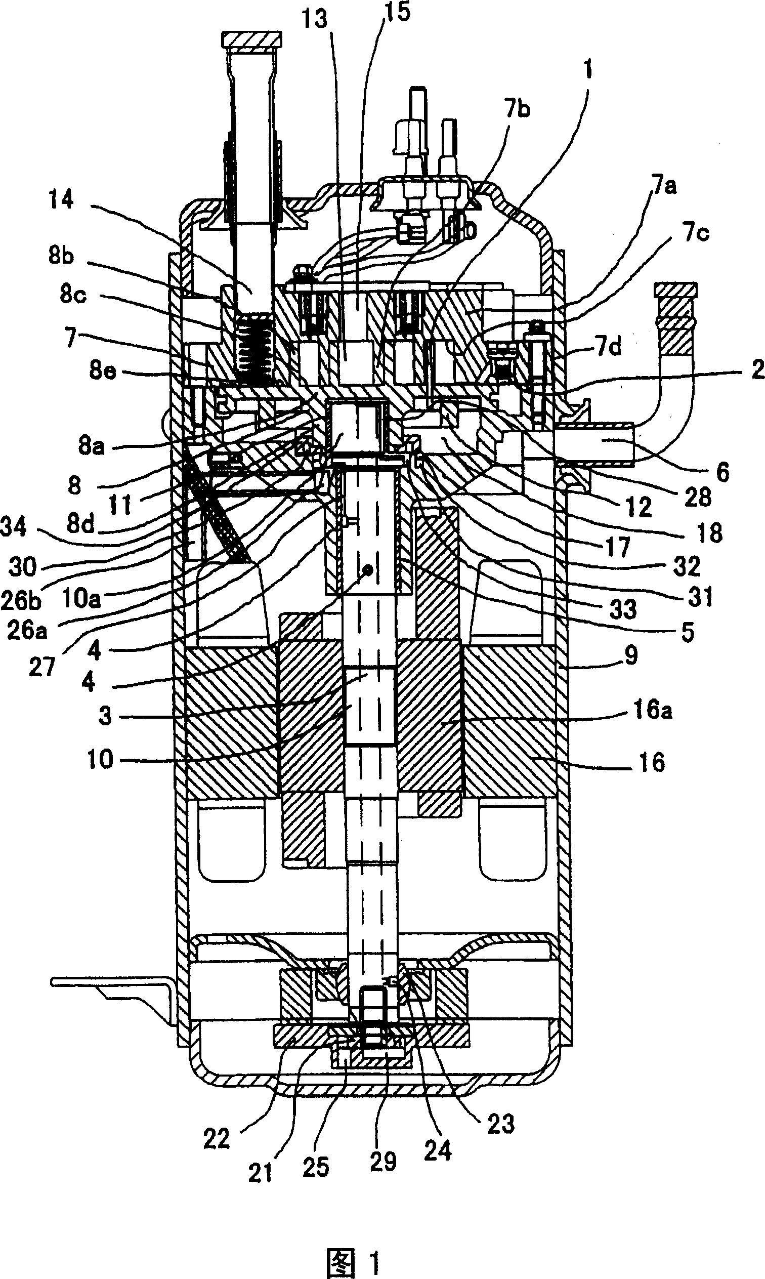
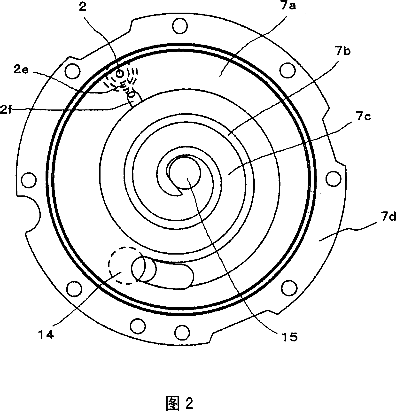
[0030] Next, the scroll compressor of the present invention will be described in detail based on the illustrated embodiments. Here, at first, Fig. 1 is a sectional view of an embodiment of the present invention, in this figure, firstly, 7 is a fixed scroll, as detailed in Fig. The roll sheet 7b erected on one side of the cover plate 7a and the support portion 7d formed in a cylindrical shape around the roll sheet 7b on the outer peripheral side of the cover plate 7a are constituted, and the roll sheet 7b of the cover plate 7a is erected. The face constitutes the dedendum 7c. Here, FIG. 2 shows the state of the fixed scroll 7 seen from the lower side of FIG. 1 .

[0031] Moreover, the support portion 7d is mounted on the frame 17 by screws or the like, and the frame 17 is mounted on the substantially cylindrical casing 9 by a fixing method such as welding, whereby the fixed scroll 7 is held in the casing. 9 in the specified position.

[0032] On the other hand, 8 is an orbit...


PUM


Abstract

The invention relates to a scroll compressor with simple structure for realizing the suppression of loss and the improvement of efficiency, including: the first space (33) for guiding lubricating oil laying up the bottom of the airtight container, which is provided on the reverse center of the circle turbination (8); the second space formed as pressure between the discharge pressure and the suction pressure, provided on the reverse of the circle turbination (8), for adjusting the pressure of the second space (18), also including a back pressure control valve (2) for making the liquid in the second space (18) break away from inhalation chamber or compression chamber via access (2f), based on difference between the pressure in the second space (18) and the pressure in the compression early days or the suction pressure guiding by access (2f) formed on the fixing turbination (7), in which, through hole is provided on the grooved tape (8b) of the circle turbination (8), so connecting the second space (18) with the compression chamber in which the mean pressure is higher than the mean pressure in the access (2f).

Description

technical field [0001] The present invention relates to a scroll compressor for compressing refrigerant gas, in particular to a scroll compressor suitable for a room air conditioner. Background technique [0002] As is well known, a scroll compressor has the following structure, using two scrolls with scroll-shaped wraps erected on a disk-shaped cover plate, and placing the wraps facing each other so that they mesh with each other. One scroll is a fixed scroll, and the other scroll is set as a spiral scroll and made to spiral, so that the volumes of multiple compression chambers formed between the coils are sequentially reduced to compress the fluid. [0003] Therefore, in the scroll compressor, when the compression operation is performed, an axial force (hereinafter referred to as pulling force) that pulls the fixed wrap and the orbiting wrap apart from each other is generated. At this time, when the two scrolls are pulled apart, a gap (gap) appears between the addendum an...

Claims


Application Information

Patent Timeline
IPC IPC(8): F04C27/00F04C18/02
CPCF04C18/0215F04C18/0292F04C28/24F04C29/023F04C29/028F04C2210/26F04C2240/40Y10S415/00Y10S417/00
Inventor 近野雅嗣大岛健一寺井利行岛田昌浩
Owner HITACHI APPLIANCES INC
Why Eureka
Try Eureka