Multi-stage rotary compressor

A technology of rotary compressor and compression unit, applied in the field of compressors, can solve the problems of increasing product cost, high price of variable-speed motors, and decreasing price competitiveness, and achieves the effects of improving efficiency, improving credibility, and reducing heat.

Inactive Publication Date: 2007-05-02
LG ELECTRONICS (TIANJIN) APPLIANCES CO LTD
View PDF0 Cites 2 Cited by
  • Summary
  • Abstract
  • Description
  • Claims
  • Application Information

AI Technical Summary

Problems solved by technology

[0014] However, when a variable-speed motor is used as the driving motor of the compressor, the price competitiveness of the variable-speed motor will decrease due to the high price of the product and the increase in product cost.

Method used


Image

  • Multi-stage rotary compressor
  • Multi-stage rotary compressor
  • Multi-stage rotary compressor

Examples


Embodiment Construction

[0050] Hereinafter, the multi-stage rotary compressor of the present invention will be described in detail with reference to the accompanying drawings.

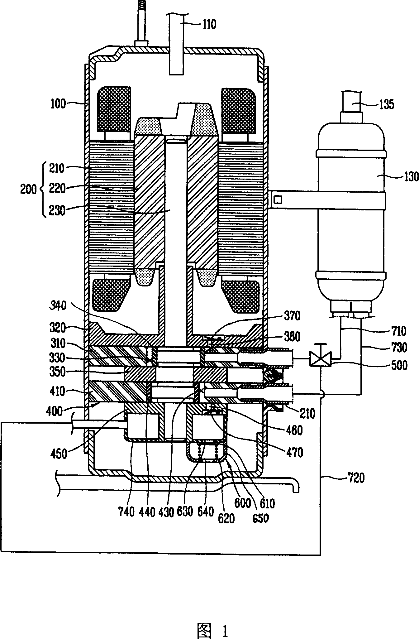
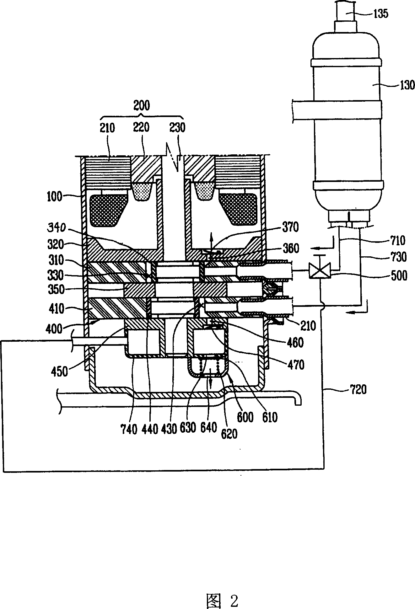
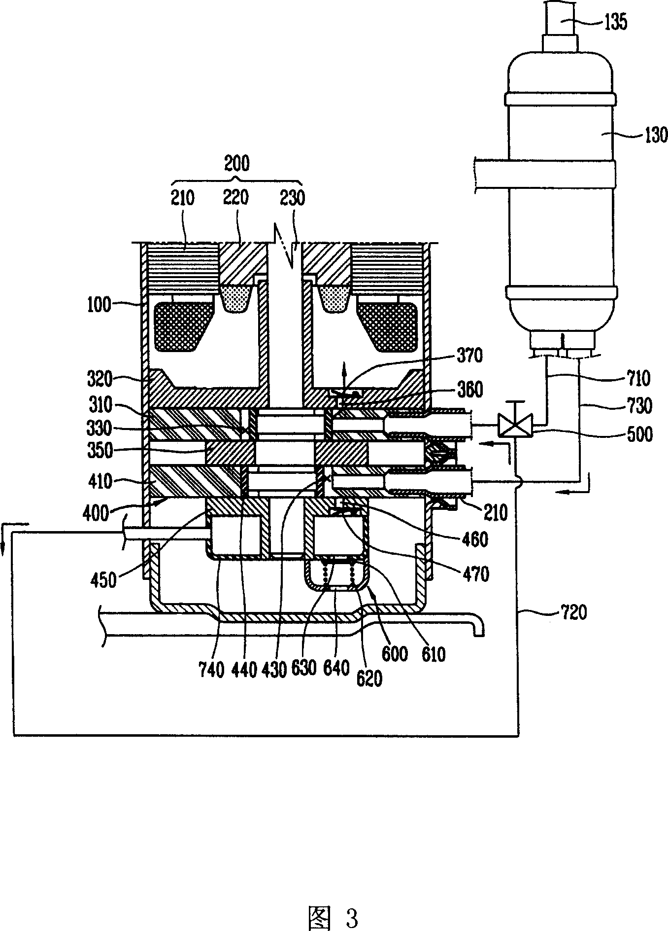
[0051] Fig. 1 is a longitudinal sectional view of a first embodiment of the present invention.

[0052]The multi-stage rotary compressor of the present invention includes a housing 100 that forms a closed space inside; a drive unit 200 that is installed in the housing 100 to generate a driving force; and receives a driving force from the driving unit 200 to compress the refrigerant. The unit 300 and the second compression unit 400; the first suction pipe 710 that guides the refrigerant to the first compression unit 300; the first control valve 500 installed on the first suction pipe 710 to control the suction amount of the refrigerant; The unit 400 guides the second suction pipe 730 of the refrigerant; the refrigerant discharged from the second compression unit 400 is temporarily stored by opening and closing the second disch...


PUM


Abstract

A multi-stage rotation compressor able to compress cold medium twice for higher compression efficiency is composed of a drive unit, the first compression unit connected with the first suction tube and the first control valve, the second compression unit connected to the second suction tube and cavity body, and the second control valve connected via connection tubes to said cavity body and the first control valve for selectively guiding cold medium.

Description

technical field [0001] The invention relates to a compressor, in particular to a multi-stage rotary compressor used in an air conditioner. Background technique [0002] An air conditioner is a device that maintains the indoor temperature at a set state and creates a pleasant indoor environment. [0003] Air conditioning includes a refrigeration cycle system. The refrigeration cycle system includes a compressor that compresses the refrigerant, a refrigerant that is compressed by the compressor, a condenser that releases heat to the outside, an expansion valve that decompresses the refrigerant condensed by the condenser, and allows the refrigerant to flow through the expansion valve. The evaporator that evaporates the refrigerant and makes it absorb external heat. [0004] The above-mentioned compressor, condenser, expansion valve and evaporator are connected to each other by connecting pipes to form a refrigeration cycle system. [0005] In the above-mentioned refrigeratio...

Claims


Application Information

Patent Timeline
Patent Type & Authority Applications(China)
IPC IPC(8): F04C23/00
Inventor 李承俊车刚旭河森哲
Owner LG ELECTRONICS (TIANJIN) APPLIANCES CO LTD
Why Eureka
Try Eureka