
Diffuser for fluid control valve and fluid control valve

A technology for fluid control valves and diffusers, which is applied in the direction of valve energy absorption devices, valve details, multi-way valves, etc., can solve the problems of small suppression or prevention effects, and achieve the suppression of cavitation and the recovery coefficient of liquid pressure Large, to avoid the effect of large-scale

Active Publication Date: 2012-07-25
YAMATAKE HONEYWELL CO LTD
View PDF6 Cites 0 Cited by
  • Summary
  • Abstract
  • Description
  • Claims
  • Application Information

AI Technical Summary

Problems solved by technology

[0009] In the vapor shift valve described in Patent Document 3, since the top of the cover-shaped diffuser has a relatively large inner angle, it suffers from the cavitation phenomenon similar to the diffuser composed of a flat perforated plate described in Patent Document 1. Problems that occur with little effect on suppression or prevention

Method used


Image

  • Diffuser for fluid control valve and fluid control valve
  • Diffuser for fluid control valve and fluid control valve
  • Diffuser for fluid control valve and fluid control valve

Examples


Embodiment Construction

[0024] Hereinafter, the present invention will be described in detail based on the embodiments shown in the drawings.

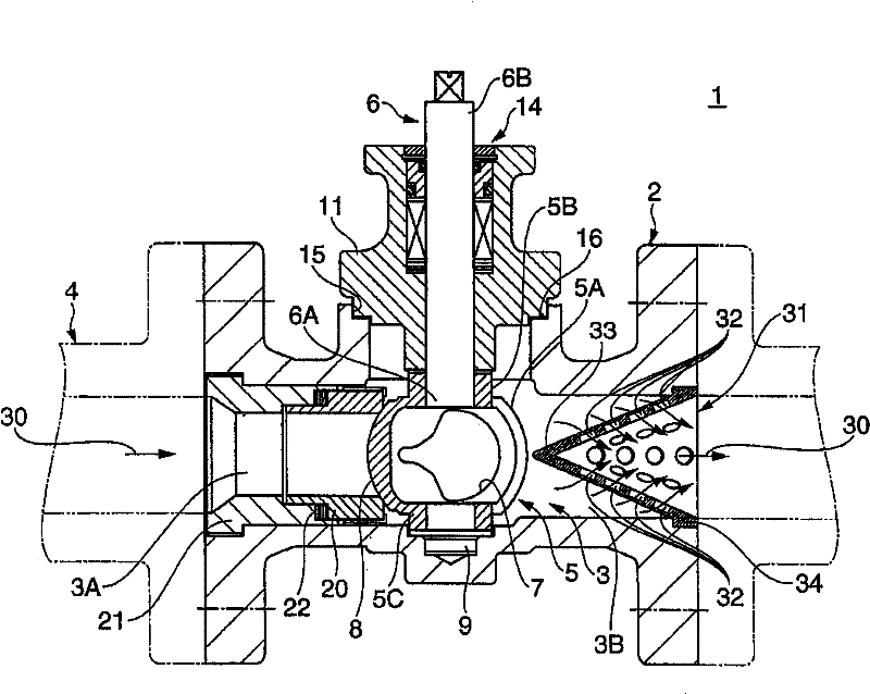
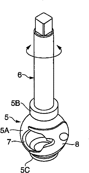
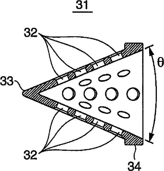
[0025] figure 1 is a cross-sectional view showing an embodiment in which the present invention is applied to a rotary valve, figure 2 is a perspective view of the spool, image 3 is the cross-sectional view of the diffuser, Figure 4 (a) to (c) are diagrams for explaining the operation of the rotary valve, (a) is a diagram showing a fully open state of a ball valve, (b) is a diagram showing an intermediate opening state, and (c) is a diagram showing a fully closed state state diagram. In these drawings, a rotary valve generally indicated by reference numeral 1 includes: a valve main body 2 having a flow path 3 constituted by a through-hole, and connected to the middle of a pipe 4; a freely rotatable valve plug 5, which is It is arranged in the center of the valve main body 2, and controls the opening and closing of the above-mentioned flow passage 3; th...


PUM


Abstract

There is provided a diffuser for fluid control valve and a fluid control valve capable of preventing or depressing cavitation phenomenon practically and depressing the reducing of the maximum flux. The diffuser 31, which is mounted inside the peristome in downstream side of the valve body 2, reduces the flow velocity of a liquid 30 and then transfers kinetic energy into pressure. The diffuser 31 is shaped as a hollow conical body with an opening bottom 34, wherein the internal angle (theta) of the top 33 is smaller than 90 DEG and a plurality of pinholes 32 is formed on side walls.

Description

technical field [0001] The present invention relates to a diffuser for a fluid control valve and a fluid control valve which decelerate the flow of fluid and convert kinetic energy into pressure. Background technique [0002] In the fluid control valve that controls the flow rate and pressure of the fluid to be controlled, when the fluid pressure is significantly reduced or the flow rate is fast, abnormal flow will occur due to the flow disorder that occurs in the throttling part of the valve. High noise, or generation of cavitation, etc. In this case, vibration and noise are likely to occur in the compressive fluid, and cavitation is likely to occur in the incompressible fluid. Once the cavitation occurs, it will cause flow reduction, valve corrosion (cavitation erosion), vibration, noise, etc., resulting in a significant decrease in valve performance, durability, and the like. [0003] Therefore, as the prior art for preventing the occurrence of the above-mentioned cavit...

Claims


Application Information

Patent Timeline
Patent Type & Authority Patents(China)
IPC IPC(8): F16K47/00F16K5/06
CPCF16K47/02F16K5/06F16K1/52
Inventor 野间口谦雄
Owner YAMATAKE HONEYWELL CO LTD
Learn More