Eureka AIR delivers breakthrough ideas for toughest innovation challenges, trusted by R&D personnel around the world.

Automatically identifying device of sensor

An automatic identification and sensor technology, applied in the direction of instruments, simulators, computer control, etc., can solve the problems of automatic control device failure, input terminal connection confusion and errors, etc., and achieve the effect of reducing on-site construction and improving work efficiency

Inactive Publication Date: 2007-04-18
智勇 +1
View PDF0 Cites 15 Cited by
  • Summary
  • Abstract
  • Description
  • Claims
  • Application Information

AI Technical Summary

Problems solved by technology

The chaotic error in the connection between each sensor and the corresponding input terminal in the control device will cause the failure of the automatic control device

Method used


Image

  • Automatically identifying device of sensor

Examples


Embodiment Construction

[0011] Below in conjunction with figure and preferred embodiment, to its specific implementation, structure, feature and effect thereof of the automatic identification device of the sensor that proposes according to the present invention, describe in detail as follows:

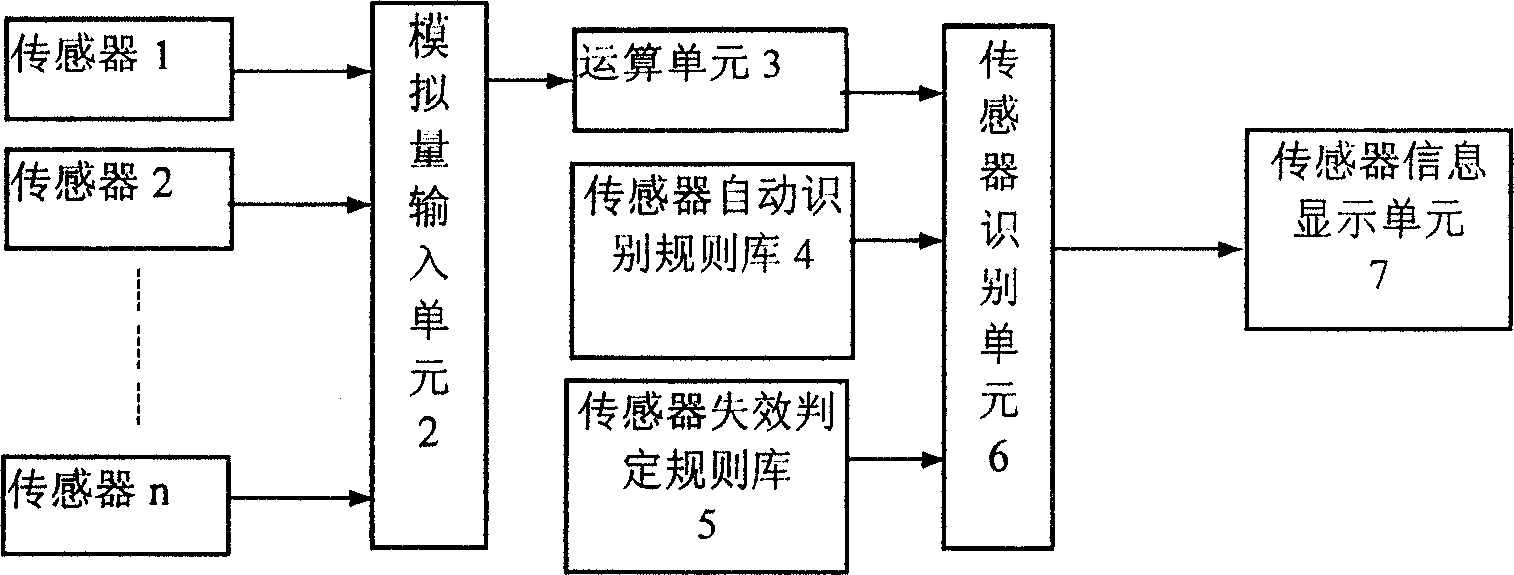
[0012] Referring to the accompanying drawings, the automatic identification device of the sensor is composed of a sensor 1, an analog input unit 2, an operation unit 3, a sensor automatic identification rule library 4, a sensor failure judgment rule library 5, a sensor identification unit 6, and a sensor information display unit 7. The output end of the sensor 1 is connected to the input end of the analog input unit 2, the output end of the analog input unit 2 is connected to the input end of the operation unit 3, the operation unit 3, the sensor automatic identification rule base 4 and the sensor failure determination rule base 5 The output end is connected to the input end of the sensor identification unit 6 ...


PUM


Abstract

The invention discloses sensor auto identification device. It includes sensor, read analog input unit, algorithm unit, sensor auto identification rule base, sensor failure decision rule base, sensor identification unit, and sensor data display unit. The output end of the sensor is connected with the input end of the read analog input unit of which output end is connected the input end of the algorithm unit. The output ends of the algorithm unit, sensor auto identification rule base, and sensor failure decision rule base are connected with the input end of the sensor identification unit of which output end is connected with the input end of the sensor data display unit. The invention needs no interface numbering mark, can automatically identify various sensor types and uses, ensure auto control device run as the given input-output relation to reduce site operation and debugging cost, increase work efficiency.

Description

technical field [0001] The invention relates to an automatic identification device when the connection relationship between a sensor and an automatic control device is wrong. Background technique [0002] The automatic control device collects various operating status information of the controlled system through various sensors, and then implements closed-loop control on the controlled system. In practical engineering applications, each sensor is connected to the corresponding input terminal in the automatic control device through a numbered standard interface. However, at the engineering site, the serial number identification is often blurred and disappears, and the engineering technical documents are difficult to obtain or even lost for a while, which will lead to a lot of manpower, material resources and time spent on identifying and determining the interface between each sensor and device connection relationship. The same situation also occurs during device monitoring a...

Claims


Application Information

Patent Timeline
Patent Type & Authority Applications(China)
IPC IPC(8): G05B19/048
Inventor 智勇吕林生
Owner 智勇
Why Eureka
Eureka Blog
Learn More