
Method for realizing self adaptive current quick break protection of power supply circuit

A current quick-break and line protection technology, which is applied in the field of current quick-break protection of power supply and distribution lines in power systems, can solve the problems of operation mode and fault type selectivity, low sensitivity, and small protection range

Inactive Publication Date: 2007-04-11
HEILONGJIANG UNIV +1
View PDF0 Cites 19 Cited by
  • Summary
  • Abstract
  • Description
  • Claims
  • Application Information

AI Technical Summary

Problems solved by technology

[0003] In order to overcome the defects that the traditional current quick-break protection cannot adapt to the power system topology, operation mode and fault type changes, its selectivity and sensitivity are low, and the protection range is small, the present invention provides an adaptive current quick-break protection for power supply and distribution lines. The implementation method of protection, which can automatically adapt to the changes of power system topology, operation mode and fault type, and provide effective protection for various phase-to-phase short-circuit faults of power supply and distribution lines

Method used


Image

  • Method for realizing self adaptive current quick break protection of power supply circuit
  • Method for realizing self adaptive current quick break protection of power supply circuit
  • Method for realizing self adaptive current quick break protection of power supply circuit

Examples


specific Embodiment approach 1

[0017] Specific Embodiment 1: The present embodiment will be specifically described below with reference to FIG. 1 . The steps of this embodiment are as follows:

[0018] Power on the digital relay protection device 101;

[0019] Assign the initial value to the reliability coefficient K of the adaptive current quick-break protection k I , The impedance Z of the unit length of the power supply and distribution line and the length of the power supply and distribution line l 102;

[0020] The measured phase current I of the power supply and distribution line k , phase voltage U k , Negative sequence current I 2 and positive sequence current I 1 value of 103;

[0021] Judging the negative sequence current I 2 Is the value greater than K times the positive sequence current I 1 The value of , where 0<K<1 104;

[0022] If the result of step 104 is yes, then the failure type coefficient K d = 3 / ...

specific Embodiment approach 2

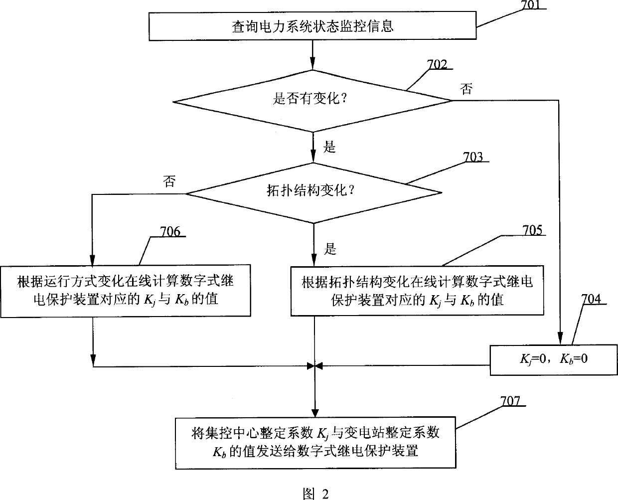
[0034] Specific implementation mode two: this implementation mode is to 107 steps in centralized control center setting coefficient k j and substation setting coefficient k b The method for determining the value will be specifically described below in conjunction with FIG. 2 in this embodiment. The steps of this embodiment are as follows: query the power system status monitoring information 701; judge whether there is a change 702; if the result of the step 702 is yes, then judge whether there is a change in the topological structure of the power system 703; if the result of the step 702 is no, then K j = 0,K b = 0 704; If the result of step 703 is yes, calculate K corresponding to the digital relay protection device online according to the topology change j with K b705; if the result of step 703 is no, calculate the K corresponding to the digital relay protection device online according to the change of the operation mode j with K b The value 706 of the centralized contr...


PUM


Abstract

This invention relates to a method for realizing protection of quick turn-off of adaptive current of supply circuit and distribution line including: electrified preparation of digital relay protection device, presenting initial value to KkI, Z and 1 to measure the values of IK, Uk, I2 and II, judging if the value of I2 is greater than that of K times of I1 (0<K<1), if so, then Kd=3 / 2, if not, the protector operates, otherwise, values of Kd, Zs, E, Kj and Kb are computed again and the value of Iset.I is determined, which computes and corrects the setting of current quick turn-off protection online to suit the topological structure of the power system, operation way and variance of fault kind.

Description

technical field [0001] The invention belongs to a protection method for various phase-to-phase short-circuit faults of a power supply and distribution line in a power system, and in particular relates to a method for realizing the current quick-break protection of a power supply and distribution line in a power system. Background technique [0002] Because the current protection principle is simple and requires few components, the current quick-break protection, as the main protection for various phase-to-phase short-circuit faults, has been widely used in power supply and distribution lines with voltage levels of 35kV and below in my country. The current setting value of the traditional current quick-break protection is calculated offline according to the maximum operation mode of the power system, and its protection sensitivity is verified according to the minimum operation mode of the power system, and remains unchanged during operation. The disadvantage of this method is...

Claims


Application Information

Patent Timeline
Patent Type & Authority Applications(China)
IPC IPC(8): H02H3/08H02H7/26
Inventor 张东中李中伟佟为明赵志衡李凤阁
Owner HEILONGJIANG UNIV
Learn More