
Rotary compactor

A compactor and indenter technology, applied in instruments, scientific instruments, measuring devices, etc., can solve the problems of complex structure, poor equipment running stability, and many running parts in the transmission part.

Inactive Publication Date: 2007-04-11
SHANDONG LUDA TEST INSTR
View PDF0 Cites 13 Cited by
  • Summary
  • Abstract
  • Description
  • Claims
  • Application Information

AI Technical Summary

Problems solved by technology

[0002] At present, in road construction projects, it is necessary to compact pavement material samples into various test pieces in order to analyze the characteristics of pavement materials. In order to better simulate the compaction effect of wheels on the road surface during the compaction process, it is necessary to use The gyratory compactor compacts the test piece while rotating. For example, the Chinese invention patent with the authorized announcement number CN250104Y discloses a gyratory compactor for compacting a material test piece, which is the same as the existing gyratory compactor. , the indenter remains horizontal during the compaction process, while the test piece is inclined at a certain angle with the test cylinder relative to the lower end surface of the indenter and performs rotary motion under the action of the corresponding driving device. There are two defects in the above-mentioned transmission structure: one is There are many moving parts in the transmission part, which leads to a more complicated structure; second, the loading mechanism is mostly realized by the motor driving the threaded screw mechanism, and the operation stability of the equipment is not good.

Method used


Image

  • Rotary compactor
  • Rotary compactor
  • Rotary compactor

Examples


Embodiment Construction

[0013] For technical content not mentioned below, relevant content in the prior art may be adopted or referred to for reference.

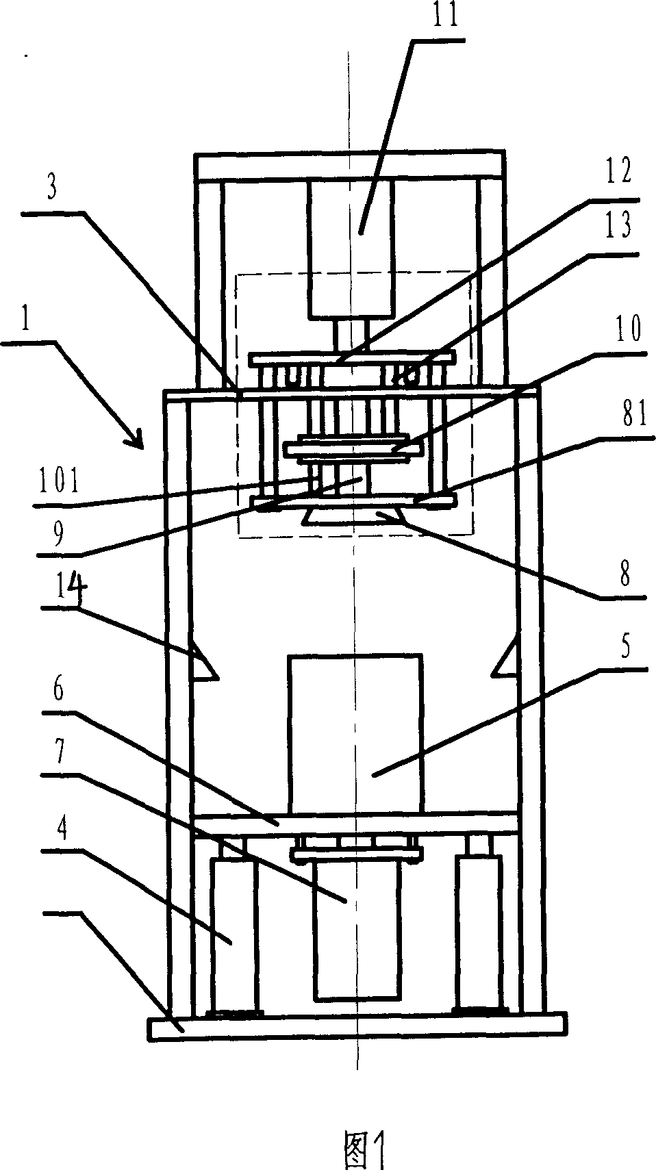
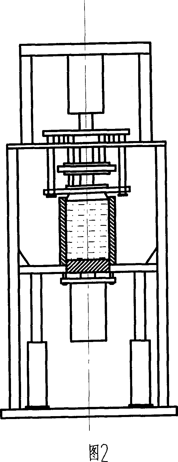
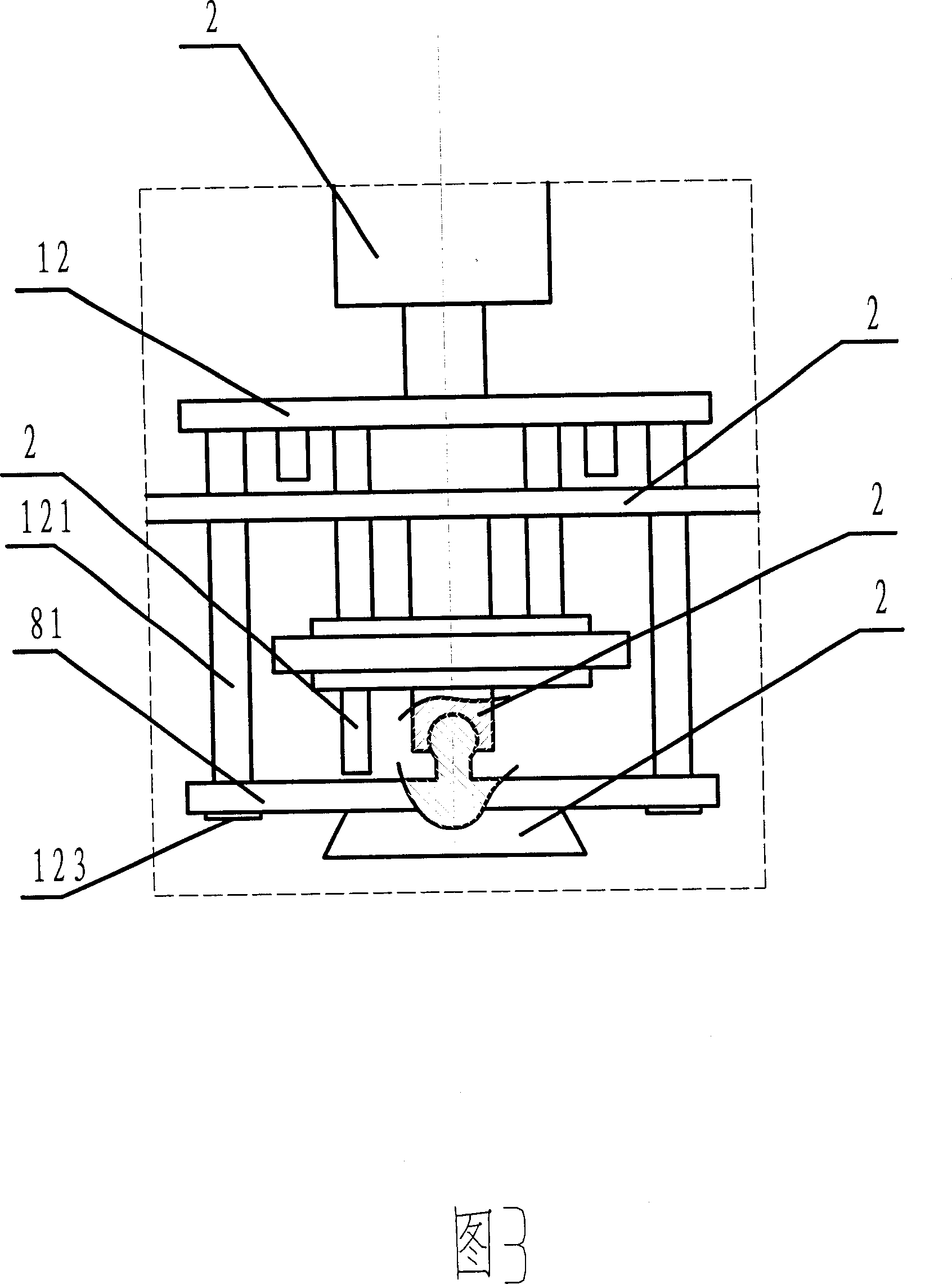
[0014] As shown in Fig. 1, the present invention has a frame 1, and the bottom of frame 1 is provided with base plate 2, and top plate 3 is provided with, and two lifting oil cylinders 4 are arranged symmetrically on both sides on the frame bottom plate 2, and the outlet of lifting oil cylinder 4 The shaft is connected with the support formwork 6 that fixes the test cylinder 5, and the support formwork 6 slides up and down in the frame 1 under the action of the lifting cylinder 4, and the support formwork 6 is provided with a support form that is equivalent to the inner diameter of the test cylinder corresponding to the test cylinder 5 hole, the lower part of the supporting mold hole is equipped with a compacting oil cylinder 7, and the upper part of the frame 1 is provided with an indenter 8 coaxially corresponding to the test cylinder 5, and the i...


PUM


Abstract

The rotary compacting instrument includes frame, bottom plate, top plate, elevating oil cylinder on the bottom plate, fixed testing drum with backup board connected to the output shaft of the elevating oil cylinder, compacting oil cylinder on the backup board, pressing head in the upper part of the frame, pressing head oil cylinder on the top plate, pressing disc fixed to the output shaft of the pressing head oil cylinder, and downward extending pressing rod in the lower part of the pressing disc, with the top plate having hole corresponding to the pressing rod. The present invention has rotary compacting to simulate the practical condition for wheel to roll the road surface and can obtain practical experiment data.

Description

technical field [0001] The invention relates to a rotary compactor used for preparing test pieces in road construction projects such as highways. Background technique [0002] At present, in road construction projects, it is necessary to compact pavement material samples into various test pieces in order to analyze the characteristics of pavement materials. In order to better simulate the compaction effect of wheels on the road surface during the compaction process, it is necessary to use The gyratory compactor compacts the test piece while rotating. For example, the Chinese invention patent with the authorized announcement number CN250104Y discloses a gyratory compactor for compacting a material test piece, which is the same as the existing gyratory compactor. , the indenter remains horizontal during the compaction process, while the test piece is inclined at a certain angle with the test cylinder relative to the lower end surface of the indenter and performs rotary motion ...

Claims


Application Information

Patent Timeline
IPC IPC(8): G01N33/42G01N3/00
Inventor 李继峰常娟侯黎常青唐飞
Owner SHANDONG LUDA TEST INSTR
Learn More