Fundus observation device, fundus image display device and memory media for fundus observation program

A fundus observation and image technology, used in fundus mirrors, eye testing equipment, medical science, etc.

Inactive Publication Date: 2007-04-04
KK TOPCON
View PDF3 Cites 24 Cited by
  • Summary
  • Abstract
  • Description
  • Claims
  • Application Information

AI Technical Summary

Problems solved by technology

[0042] However, with the conventional fundus observation device, it is not easy to grasp the mutual positional relationship between the two-dimensional image of the fundus surface of the subject's eye obtained by the fundus camera and the tomographic image of the fundus obtained by the optical image measuring device. It is difficult to grasp the state of the gaze part in detail

Method used


Image

  • Fundus observation device, fundus image display device and memory media for fundus observation program
  • Fundus observation device, fundus image display device and memory media for fundus observation program
  • Fundus observation device, fundus image display device and memory media for fundus observation program

Examples


Embodiment Construction

[0150] Hereinafter, an example of a preferred embodiment of the fundus observation device, the fundus image display device, and the fundus observation program of the present invention will be described in detail with reference to the drawings. In addition, the same components as before are denoted by the same symbols as those used in FIGS. 42 and 43 .

[0151]

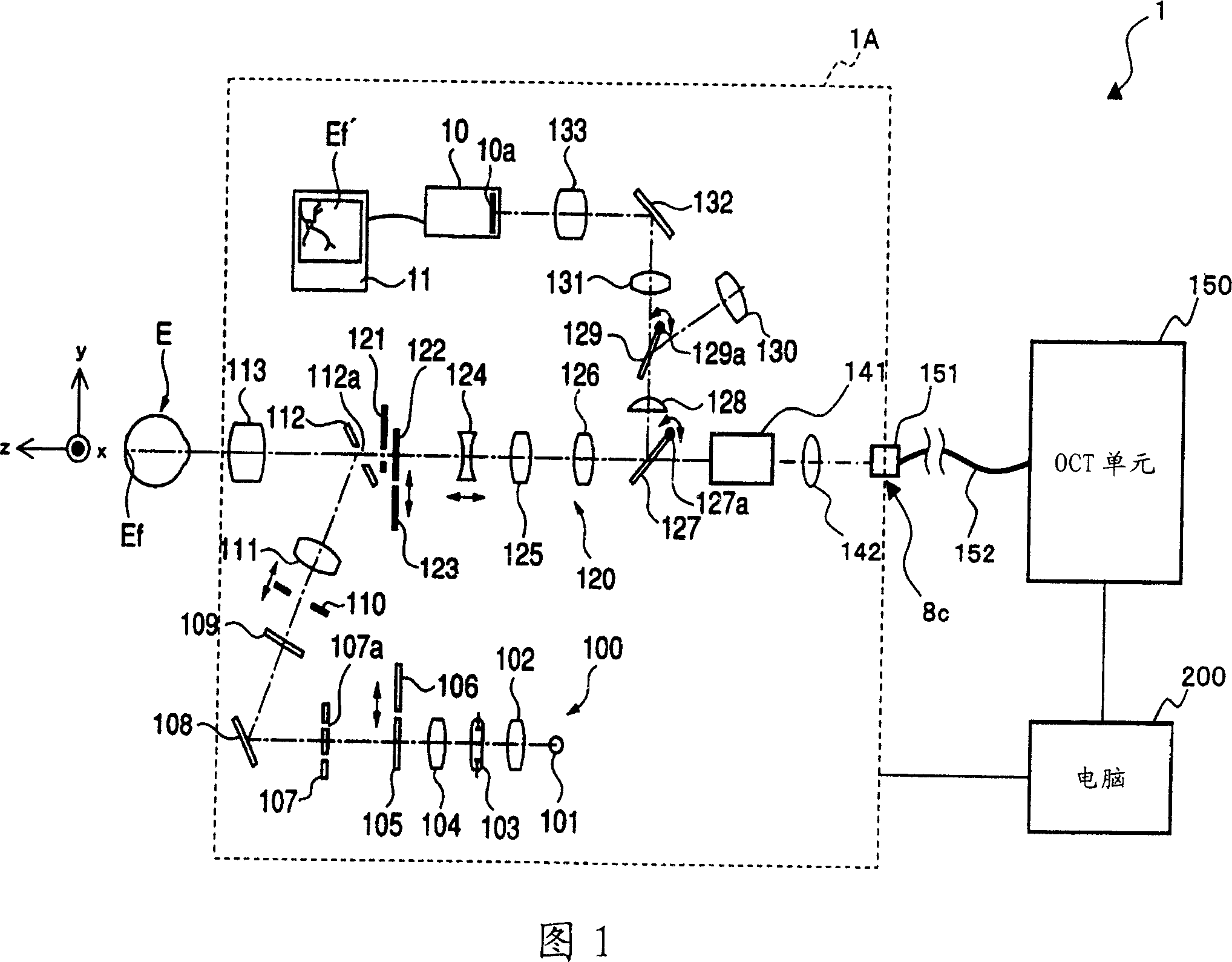
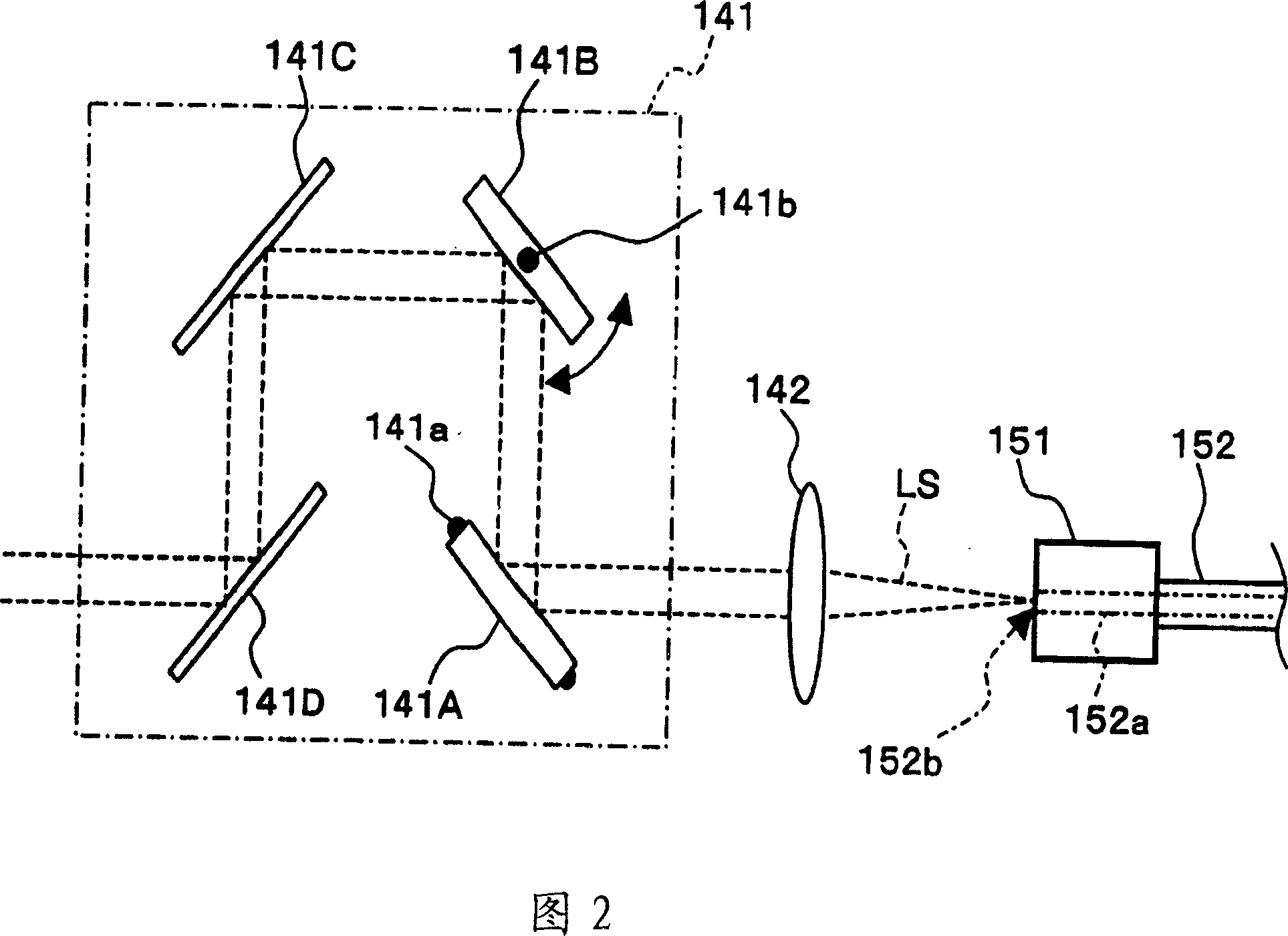
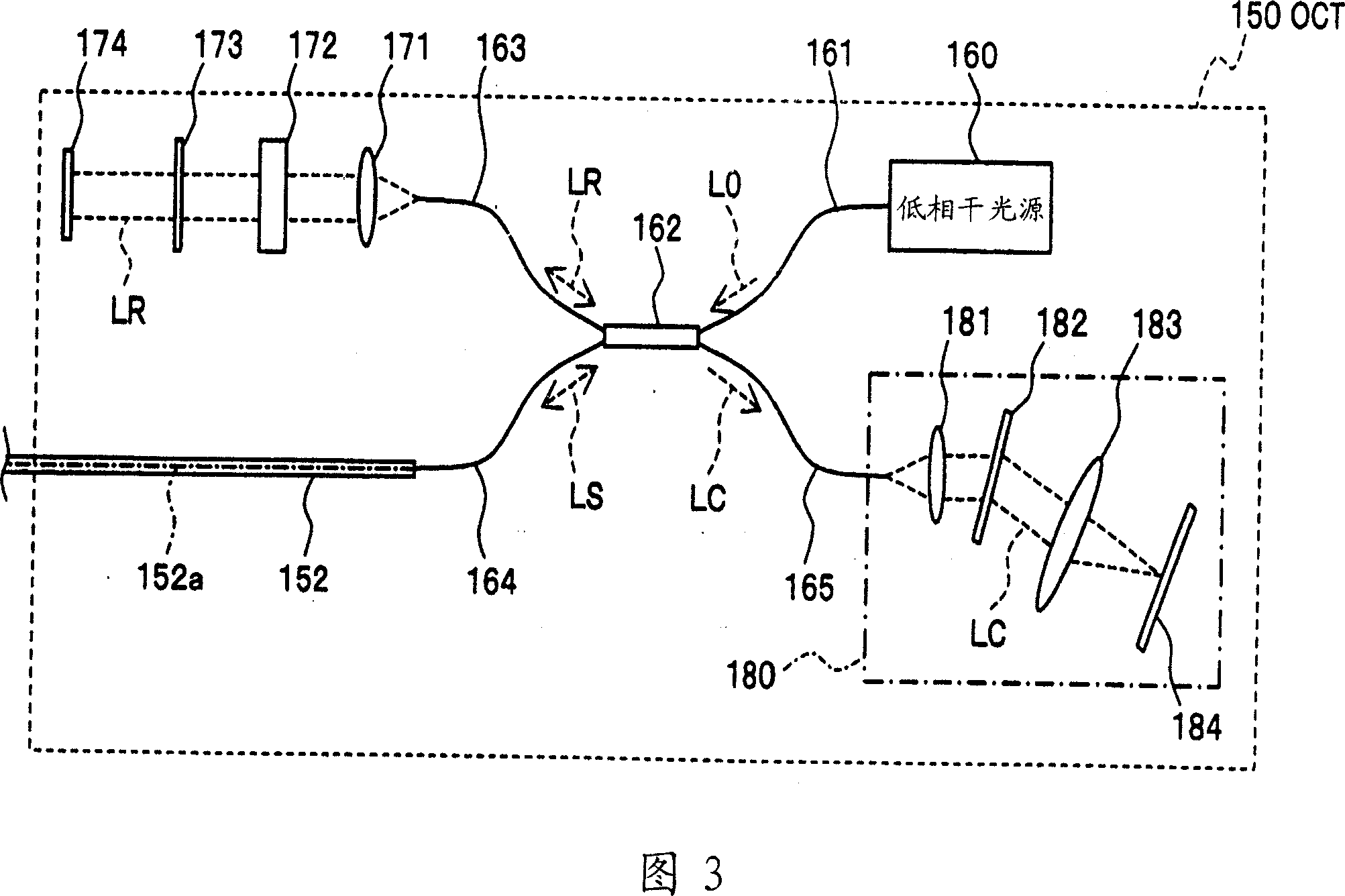
[0152] First, the configuration of a first embodiment of the fundus observation device of the present invention will be described with reference to FIGS. 1 to 5 . FIG. 1 shows the overall configuration of a fundus observation device 1 according to this embodiment. FIG. 2 shows the configuration of the scanning unit 141 in the fundus camera unit 1A. FIG. 3 shows the structure of the OCT unit 150 . FIG. 4 shows the hardware configuration of the computer 200 . FIG. 5 shows the structure of the control system of the fundus observation device 1 .

[0153] [the whole frame]

[0154] As shown in FIG. 1 , the fundus obs...


PUM


Abstract

To provide a technology that makes it easy to capture a positional relation of a 2-dimensional image of the surface of a fundus oculi and a tomographic image of the fundus oculi. The fundus observation device 1 is provided with a fundus camera unit 1A for forming a 2-dimensional image of the surface of a fundus oculi Ef of an eye to be examined, an OCT unit 150 for forming a tomographic image of the fundus oculi Ef, a scanning unit 141 as well as an image processing part 220, a display 207, and a controlling part 210 of a computer 200 for displaying the 2-dimensional image formed by the fundus camera unit 1A and a tomographic image formed by the OCT unit, etc. in parallel on the display 207, and also for displaying the cross-sectional position information (attention line L, attention region P) indicating the cross-sectional position of the tomographic image on the surface of the fundus oculi Ef, so as to be overlapped with the 2-dimensional image.

Description

technical field [0001] The present invention relates to a fundus observation device, a fundus image display device, and a storage medium storing a fundus observation program for observing the state of the fundus of an eye to be inspected. Background technique [0002] As a fundus observation device, a fundus camera has conventionally been widely used. FIG. 42 shows an example of an external configuration of a conventional general fundus camera, and FIG. 43 shows an example of an optical system configuration built therein (for example, refer to Patent Document 1.). In addition, the term "observation" includes at least observation of a captured image of the fundus (in addition, observation of the fundus with the naked eye may also be included). [0003] First, referring to FIG. 42 , the appearance structure of a conventional fundus camera 1000 will be described. The fundus camera 1000 includes a gantry 3 mounted on a base 2 so as to be slidable in front, rear, left, and righ...

Claims


Application Information

Patent Timeline
Patent Type & Authority Applications(China)
IPC IPC(8): A61B3/12
CPCA61B3/102A61B3/12
Inventor 塚田央春本考树青木弘幸木川勉福间康文
Owner KK TOPCON
Why Eureka
Try Eureka