


Quick Research
Generate reliable direction feasibility study reports for your R&D in just a few steps.

Technical Q&A
Discover and master advanced knowledge NOW. Basics, ideas, possibilities, all at once.

Find Solutions
As an expert in R&D theories, this can generate solutions to your technical problems instantly.

Evaluate Feasibility
Analyze your overall solution with one click, know your potential R&D risks in advance.

Monitor Landscape
Get weekly tech updates, stay abreast of the latest tech innovations and key insights.
Filter plate of filter press and method of manufacturing the same
A filter press and filter plate technology, applied in the field of filter plate and its manufacturing, can solve the problems of increased wall thickness, heavy weight, heavy weight, etc.
- Summary
- Abstract
- Description
- Claims
- Application Information
AI Technical Summary
Problems solved by technology
Method used
Image

Examples
no. 1 Embodiment
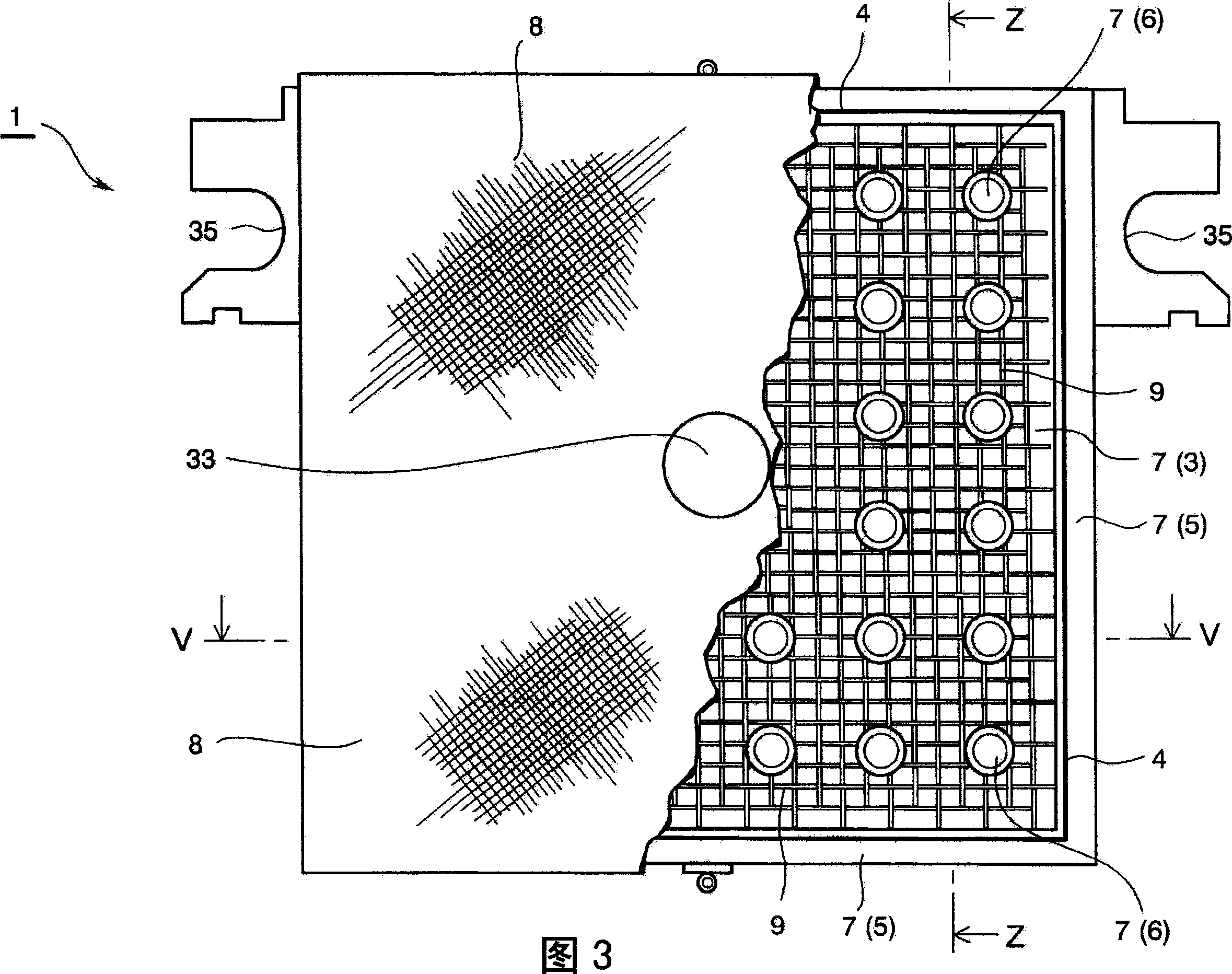
[0166] First, the general structure of the filter plate of the first embodiment of the present invention will be introduced according to FIGS. 3-6.
[0167] Fig. 3 is a front view showing the filter plate 1 of the first embodiment of the present invention (showing the state after cutting a part of the filter cloth 8);
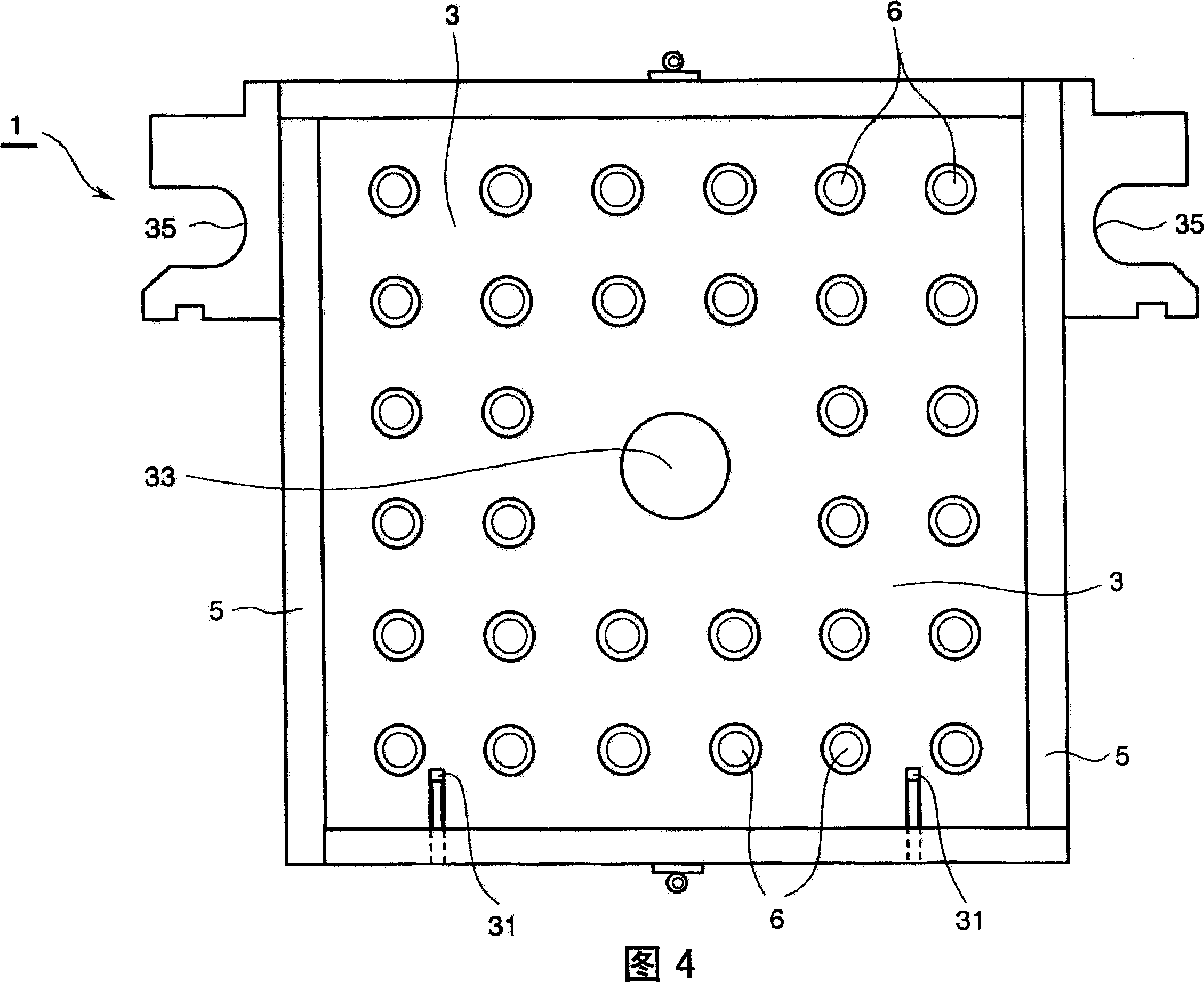
[0168] Fig. 4 shows the state after the covering part 7, filter cloth 8 and mesh 9 are removed from the filter plate 1 shown in Fig. 3;
[0169] Fig. 5 is a cross-sectional view along the V-V line in Fig. 3, and the surroundings of the opposite frame parts 5, 5 clamping the filter plate main body 3 are enlarged and displayed;
[0170] Fig. 6 is a cross-sectional view along the line V-V in Fig. 3 , which enlarges and displays the surroundings of the opposing gaskets 6, 6 clamping the filter plate main body 3;
[0171] As shown in Figures 3 to 6, the filter plate 1 of the present invention has a filter plate main body 3 formed as a substantially square iron flat...
no. 2 Embodiment
[0213] The filter plate of the second embodiment of the present invention will be described below with reference to FIGS. 12 and 13 .
[0214] Fig. 12 is a front view showing the filter plate 1 of the second embodiment, showing a state where the covering member 7, the filter cloth 8 and the mesh 9 are removed from the filter plate.
[0215] FIG. 13 is a cross-sectional view showing the filter plate 1 according to the second embodiment, showing the periphery of the frame member 5 in an enlarged manner.
[0216] Furthermore, the description of the same parts as those of the above-mentioned first embodiment is omitted, and only the main points of difference are described.
[0217] In the filter plate 1 of the second embodiment, the O-ring 4 is made of the same material as the covering member 7 and is integrally formed. The frame member 5 is formed by frame assembling four elements having the same shape and the same size. As shown in FIGS. 12 and 13 , the frame member is arrange...
no. 3 Embodiment
[0219]The filter plate of the third embodiment of the present invention will be introduced below with reference to FIG. 14 . FIG. 14 is a cross-sectional view showing a filter plate according to a third embodiment of the present invention, showing the periphery of the frame member 5 in an enlarged manner. Furthermore, the description of the same parts as those of the above-mentioned second embodiment is omitted, and only the main points of difference are described.
[0220] In the filter plate of the third embodiment, the recessed portion 55 is formed in the frame member 5 along the longitudinal direction. When welding the frame member 5 to the filter plate main body 3 , as shown in FIG. 13 , the end of the filter plate main body 3 is fitted into the recess 55 .
PUM
| Property | Measurement | Unit |
|---|---|---|
| diameter | aaaaa | aaaaa |
Abstract
Description
Claims
Application Information
 - R&D Engineer
- R&D Manager
- IP Professional
- Industry Leading Data Capabilities
- Powerful AI technology
- Patent DNA Extraction
Browse by: Latest US Patents, China's latest patents, Technical Efficacy Thesaurus, Application Domain, Technology Topic, Popular Technical Reports.
© 2024 PatSnap. All rights reserved.Legal|Privacy policy|Modern Slavery Act Transparency Statement|Sitemap|About US| Contact US: help@patsnap.com