
Magnetic machine

A magnetic motor and moving magnet technology, applied in the direction of generators/motors, electrical components, etc., can solve the problems of low magnetic energy density and difficulty in large-scale operations, and achieve the effects of low cost, convenient maintenance, and simple mechanical structure

Inactive Publication Date: 2007-03-28
董新武
View PDF0 Cites 3 Cited by
  • Summary
  • Abstract
  • Description
  • Claims
  • Application Information

AI Technical Summary

Problems solved by technology

At that time, the permanent magnet was natural iron ore (Fe 3 o 4 ), the magnetic energy density is too low, and it is difficult to make a big difference

Method used


Image

  • Magnetic machine
  • Magnetic machine
  • Magnetic machine

Examples


Embodiment Construction

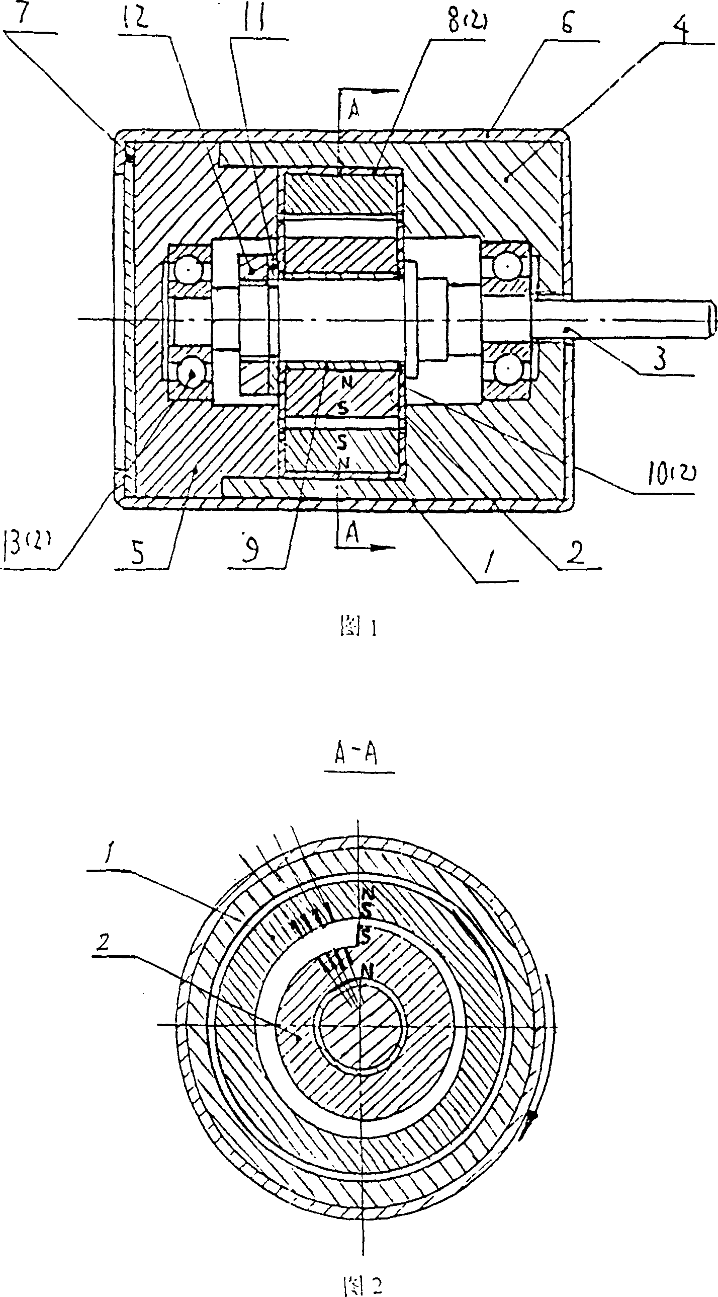
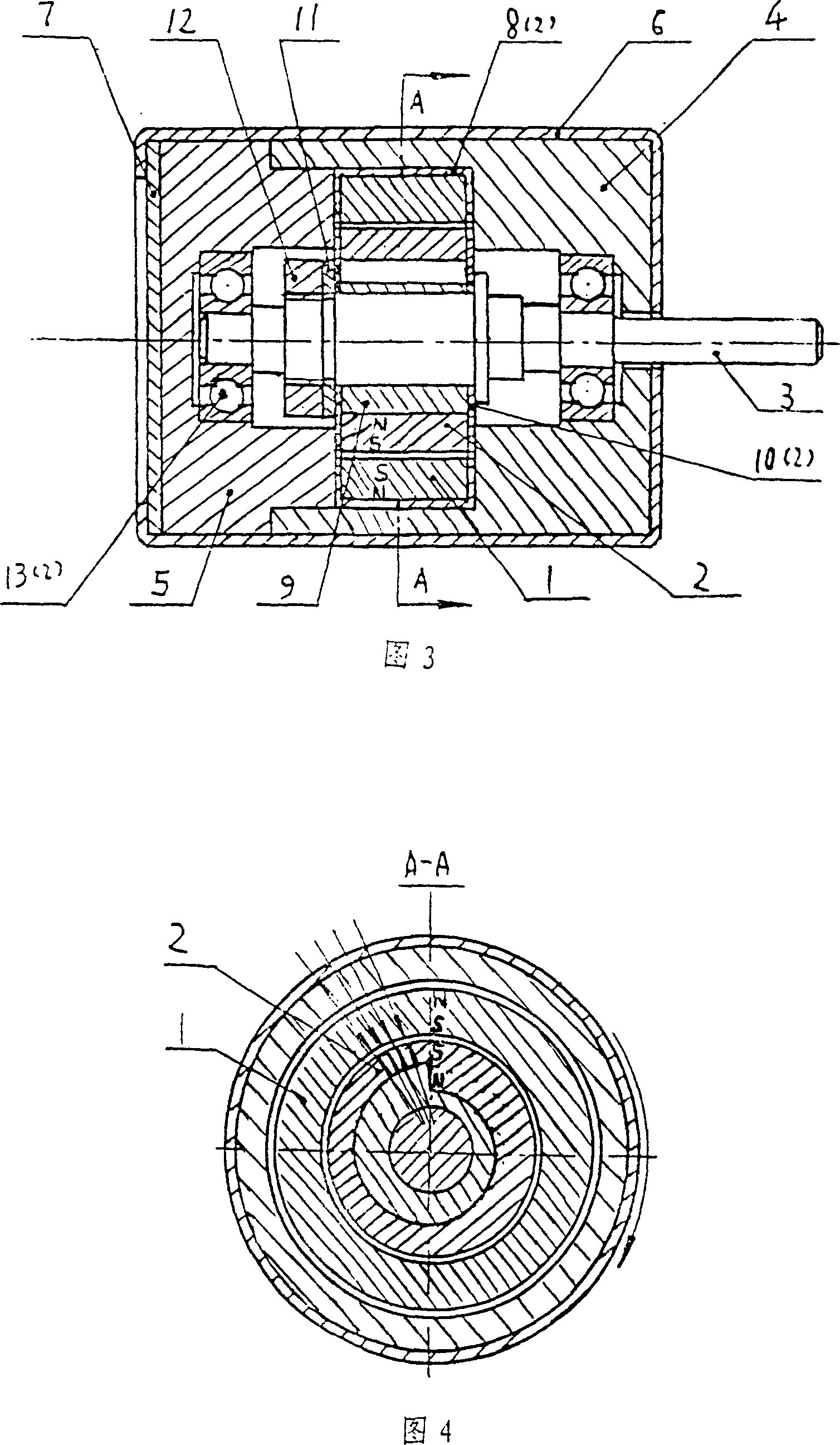
[0104] For magnetic motor products, take the schematic diagram of the magnetic motor (A) in Figure 1 as an example, and assemble it step by step:

[0105] 1. Put one of the bearings (13) into the bearing housing (4);

[0106] 2. Wrap the fixed magnetic ring (1) tightly with two fixed bushes (8);

[0107] 3. Put the tight fixed magnetic ring (1) into the bearing seat (4) and fix it;

[0108] 4. Squeeze the bearing seat (4) into the outer cover (6);

[0109] 5. Put one piece of moving gasket (10) on the shaft (3);

[0110] 6. Install the A moving bush (9) on the shaft (3) and tighten it;

[0111] 7. Fix the A moving magnetic ring (2) on the A moving bushing (9);

[0112] 8. Put the other moving gasket (10) on the shaft (3);

[0113] 9. Install the washer (11) on the outside of the movable washer (10) on the shaft (3);

[0114] 10. Put the fastening nut (12) on the shaft (3) and screw it with its thread, and fasten the A moving magnetic ring (2);

[0115] 11. Put the end o...


PUM


Abstract

Stator and rotor cirques of magnetic motion machine (MMM) are made of Nd-Fe-B material and are formed in directional magnetic field. Stator cirque is round. Rotor has one side adopting the shape of Archimedes helical line. Stator and rotor cirques radial eccentricity leaning-angle evenly radiation magnetized. The like magnetic poles get together to produce huge radial eccentricity leaning-angle evenly descending uneven repel force to drive the MMM to do work. This special magnetizer clamps includes knife-shape silicon-steel sheets and windings. After inducing current, it produces radial eccentricity leaning-angle strong magnetic field to form directionally and magnetize cirques. The greatest advantage of MMM is the millions of millions co-direction electrons of iron in cirques circulate rapidly and restlessly around the nucleus to produce magnetic forces for long time. These magnetic forces are collected together to form a huge repel force to drive MMM without outer energy.

Description

technical field [0001] The invention relates to a magnetic motor and a special magnetizer fixture used in a method for magnetizing a magnetic ring of the magnetic motor, and belongs to the technical field of power machinery using permanent magnetic repulsion as a rotating power source. technical background [0002] Our ancestors discovered the permanent magnet phenomenon as early as three thousand years ago, and the appearance of the compass is a great invention of the practical application of permanent magnets. At that time, the permanent magnet was natural iron ore (Fe 3 o 4 ), the magnetic energy density is too low, and it is difficult to make a big difference. [0003] With the rapid development of science and technology, a large amount of energy is continuously consumed, and the use of green and non-polluting environmentally friendly energy is very popular. The successful development and popularization of strong magnetic materials such as NdFeB rare earth permanent ma...

Claims


Application Information

Patent Timeline
Patent Type & Authority Applications(China)
IPC IPC(8): H02N11/00
Inventor 董新武
Owner 董新武
Learn More