
Permanent magnet type rotating electric machine capable of suppressing deformation of rotor core

A technology of rotating electrical machines and permanent magnets, applied in the direction of magnetic circuit shape/style/structure, magnetic circuit, electromechanical devices, etc., can solve the problems of unable to maintain the strength of the bridge and affect the reliability of rotating electrical machines, so as to ensure reliability and suppress Effects that deform and increase degrees of freedom

Active Publication Date: 2007-03-28
TOYOTA JIDOSHA KK
View PDF7 Cites 38 Cited by
  • Summary
  • Abstract
  • Description
  • Claims
  • Application Information

AI Technical Summary

Problems solved by technology

However, since the aforementioned stress remains therein, the strength of the bridge portion cannot be maintained, which affects the reliability of the rotating electric machine

Method used


Image

  • Permanent magnet type rotating electric machine capable of suppressing deformation of rotor core
  • Permanent magnet type rotating electric machine capable of suppressing deformation of rotor core
  • Permanent magnet type rotating electric machine capable of suppressing deformation of rotor core

Examples


no. 1 example

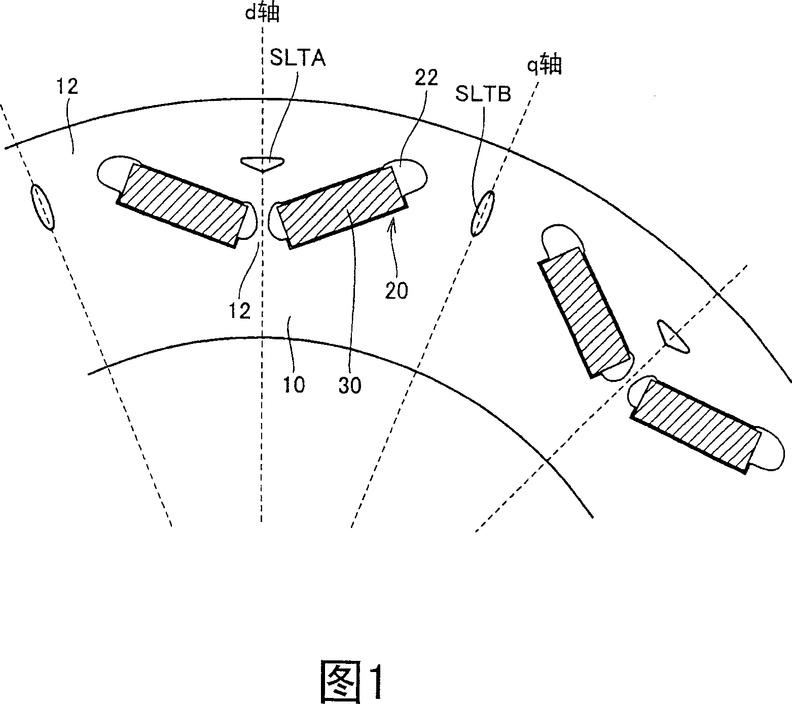
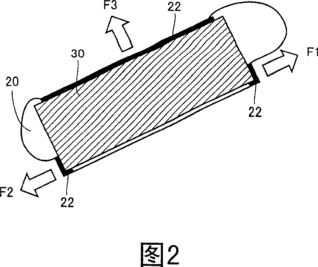
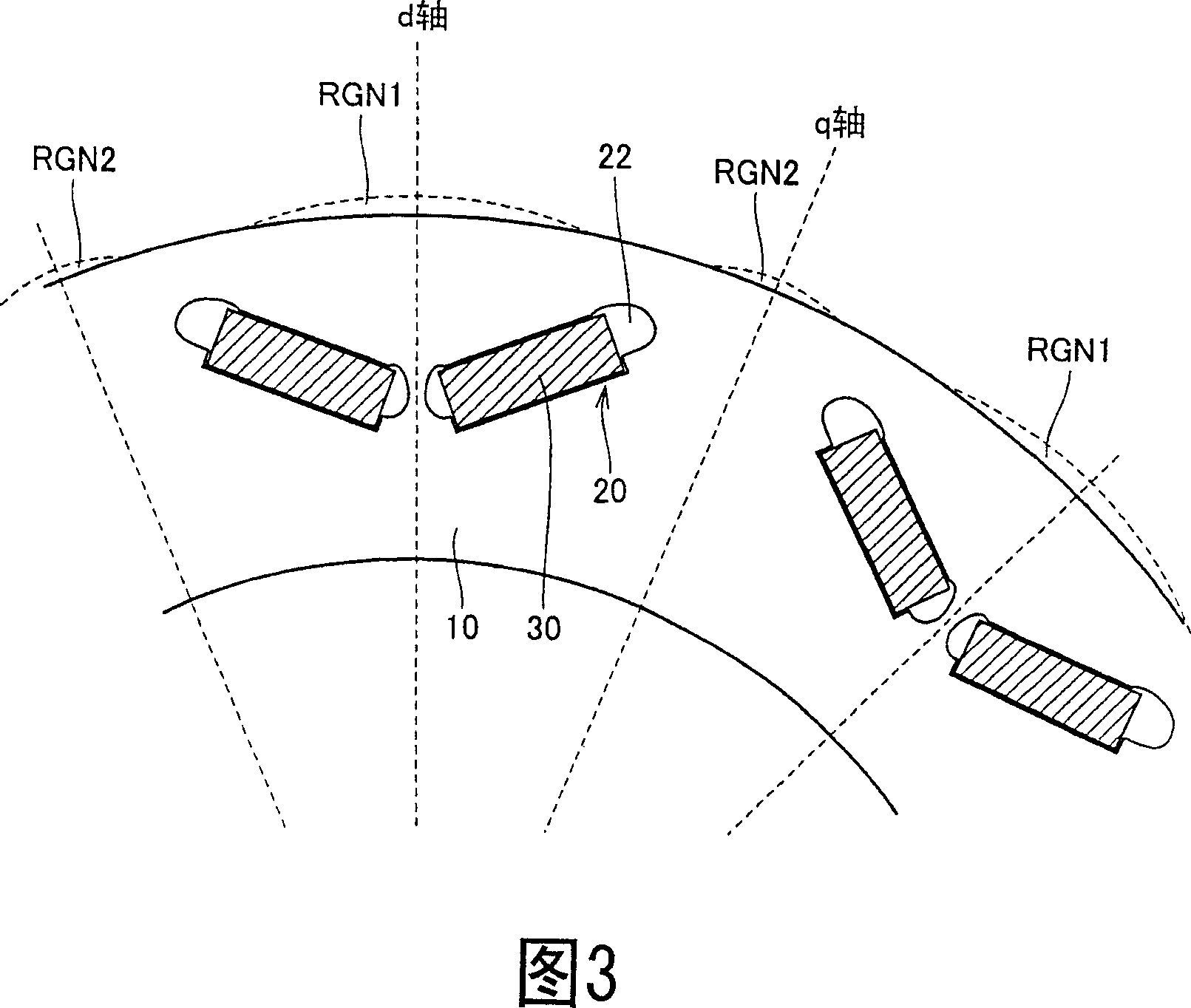
[0041] FIG. 1 is a diagram for describing the structure of a rotor in a permanent magnet type rotating electric machine according to a first embodiment of the present invention. Fig. 1 is an enlarged view of a rotor viewed from the direction of the rotation axis.

[0042] Referring to FIG. 1 , the rotor includes a rotor core 10 disposed at an outer periphery of a rotating shaft, not shown, and a permanent magnet 30 disposed at the rotor core 10 .

[0043] The rotor core 10 is formed of, for example, a plurality of electromagnet pieces stacked in the rotation axis direction of the rotor. The openings 20 are provided in plural numbers along the circumferential direction of the rotor core 10 . When the electromagnet plates are punched to obtain thin plates forming the rotor core 10, the openings 20 are simultaneously punched and formed parallel to the rotation axis as the thin plates are stacked.

[0044]As shown in FIG. 1 , the openings 20 are arranged at the outer peripheral ...

no. 2 example

[0089] Fig. 8 is a diagram for describing the structure of a rotor in a permanent magnet type rotating electric machine according to a second embodiment of the present invention.

[0090] Referring to FIG. 8 , the rotor core 10c includes a plurality of openings 20 and caulking members 40A and 40B. The rotor core 10c in FIG. 8 corresponds to the rotor core 10 in FIG. 1, and the slits SLTA, SLTB thereof are replaced by riveting members 40A and 40B.

[0091] Specifically, as shown in FIG. 9 , each of the caulking members 40A and 40B has a caulking portion protruding in the rotation axis direction and a slit SLTE provided continuously to the caulking portion. When the electromagnetic steel sheet is punched to obtain thin plates forming the rotor core 10 , the caulking portion and the slit SLTE are simultaneously formed and formed parallel to the rotation axis as the thin plates are stacked. By riveting the stacked electromagnetic steel sheets, adjacent electromagnetic steel sheet...


PUM


Abstract

Provided is a permanent magnet type rotating electric machine. A rotor core is provided with a plurality of slits extending in the rotation shaft direction, independently of openings. The first slit is arranged at the center of the magnetic pole of the rotor core to be capable of absorbing stress acting on an inner circumferential surface of each opening in a direction normal to a main surface of a permanent magnet. The second slit is arranged between the magnetic poles of the rotor core to be capable of absorbing stress acting in parallel with the main surface of the permanent magnet. Thus, the rotor core is prevented from deforming in a radial outward direction. Further, by forming the first and second slits each in a form not interfering the magnetic path of the magnetic flux by the stator passing inside the rotor core, the motor performance is ensured.

Description

technical field [0001] The present invention relates to a permanent magnet type rotating electrical machine, and more particularly, to a permanent magnet type rotating electrical machine having permanent magnets embedded in a rotor. Background technique [0002] In the rotor of the permanent magnet type rotating electric machine, for example, as shown in FIG. -104962, 09-215236, 2002-034187, 08-237893, 2001-286109 and 2004-254466). Then, the rotor is driven to rotate based on the rotating magnetic field generated by bringing the coils arranged around the rotor core 100 on the not-shown stator side into a conductive state. Since the magnetic field is generated for each designated pole by the permanent magnet 130, a larger output is obtained with a smaller configuration. [0003] In the permanent magnet type rotating electric machine thus configured, usually the permanent magnets are fixed by an adhesive filled in each opening 120 of the rotor core 100 . However, with this ...

Claims


Application Information

Patent Timeline
Patent Type & Authority Applications(China)
IPC IPC(8): H02K1/27
CPCH02K1/2766
Inventor 服部宏之
Owner TOYOTA JIDOSHA KK
Learn More