
Novel backlight clock

A backlight and clock technology, which is applied in the field of new backlight clocks, can solve problems such as uneven light distribution, uneven backlight distribution, and high production costs, and achieve the effects of convenient viewing of time, non-glare light, and good environmental performance

Inactive Publication Date: 2007-03-28
邵力民
View PDF1 Cites 1 Cited by
  • Summary
  • Abstract
  • Description
  • Claims
  • Application Information

AI Technical Summary

Problems solved by technology

Such a result is too complicated, the production cost is high, and the backlight distribution is uneven, which does not look very beautiful
[0003] There are also some clocks that simply add some light sources, or set light-emitting devices on the pointer to achieve the effect of night vision. The structure is very simple, but the light distribution is not uniform, and it will be too bright at night, and even glare affects sleep.

Method used


Image

  • Novel backlight clock

Examples


Embodiment

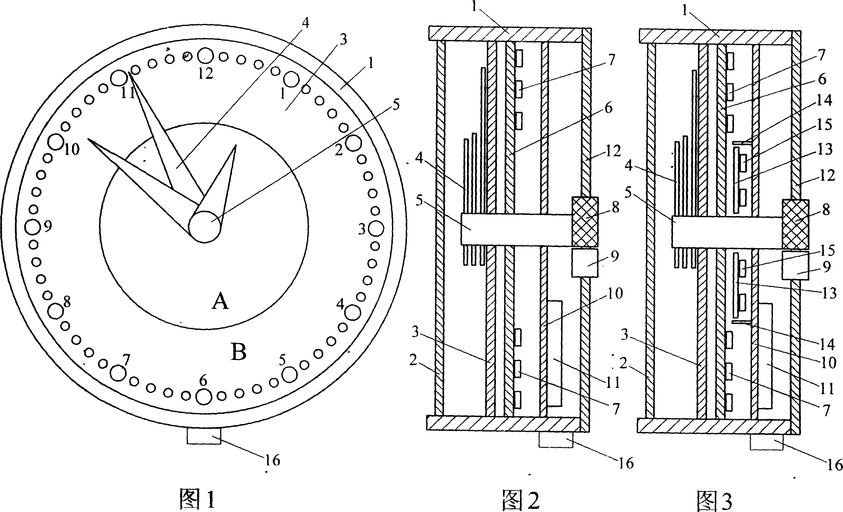
[0013] Example: Referring to Figures 1 and 2, the present invention is provided with a clock panel 3 inside the housing 1, a transparent front cover 2 is provided on the front of the clock panel 3, and a clock hand 4 is provided at the end of the mandrel 5 of the clock panel 3. The central area of ​​the clock panel 3 close to the mandrel 5 is set as the light-transmitting area A, the area outside the light-transmitting area A is set as the light-shielding area B, and the time index and the index number on the light-shielding area B are set to be light-transmissive; A diffuser plate 6 is arranged inside the clock panel 3, and a number of LED luminous bodies 7 are arranged on the back of the diffuser plate 6. The diffuser plate 6 can evenly diffuse the light of the LED luminous bodies 7 so that the brightness of the clock panel 3 is basically the same; There is a reflective plate 10 inside. The front of the reflective plate 10 is set as a reflective surface, and the reflective surfa...


PUM


Abstract

This invention provides a new kind of back clock. The new kind of clock has a transmission area A in the center of face plate. There is a shading area B around the transmission areaA, in which the hour graduated points and graduated numbers are non-light tight. The astigmatism plate which includes some LED fluophors is inside of the face plate. There is a reflector inside of the astigmatism plate; in the meantime, there is reflecting surface in the front of the reflector and circuit board which controls the LED fluophors in the back of the reflector. The end part of mandrel is in the module which is nearby battery case. The battery case is used to support the LED fluophors or instead of the electricity which is come from the power interface. There is an adjustable knob which can control the brightness of LED fluophors in the shell. In order to improvement, there is a poster board between the astigmatism board and the reflector. There is some LED fluophors in the back of poster board and shading board around it.

Description

Technical field [0001] The invention relates to a new type of backlight clock, in particular to the improvement of the clock panel and its backlight source and other structures. Background technique [0002] In the prior art, in order to easily know the time of the clock at night, those skilled in the art have made great improvements to the clock structure and added some background lighting devices. For example, an application file named "LCD Clock" (Patent Application No. 200420014188.7) discloses a LCD clock including a real-time clock circuit, a liquid crystal display, a backlight device, a backlight control circuit, and a The power supply device, a main control unit electrically connected to the backlight control circuit and the power supply device, wherein the real-time clock circuit outputs real-time information to the main control unit, the liquid crystal display includes at least one area to display real-time information, and the background lighting device includes a plur...

Claims


Application Information

Patent Timeline
Patent Type & Authority Applications(China)
IPC IPC(8): G04B19/30G04B19/06G04B45/00G04C3/00G04C10/00
Inventor 邵力民
Owner 邵力民
Learn More