
Antenna configuration

An antenna and configuration technology, applied in antennas, resonant antennas, electrical short antennas, etc., can solve problems such as small bandwidth, and achieve the effect of increasing bandwidth and reducing size

Inactive Publication Date: 2007-03-21
NXP BV
View PDF1 Cites 3 Cited by
  • Summary
  • Abstract
  • Description
  • Claims
  • Application Information

AI Technical Summary

Problems solved by technology

For example, in most antenna configuration designs, smaller antenna configurations result in smaller bandwidth

Method used


Image

  • Antenna configuration
  • Antenna configuration
  • Antenna configuration

Examples


Embodiment Construction

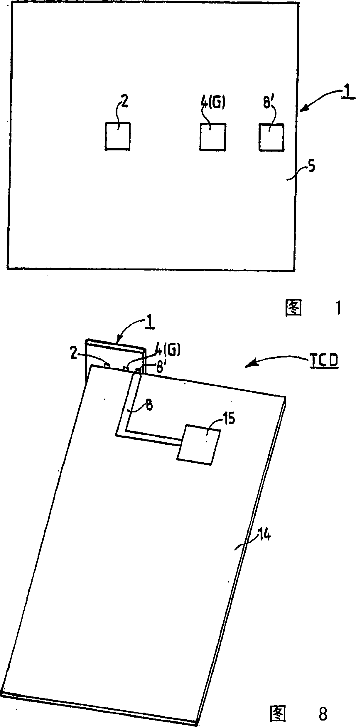
[0037] Figure 1 shows a 12 x 11 x 1mm 3 And utilize the embodiment of the antenna configuration 1 manufactured by LTCC technology. The antenna configuration 1 comprises a dielectric substrate 5 which is essentially made of ceramic and which contains an antenna structure AS (not shown in FIG. 1 ) inside it. In more detail, the dielectric matrix 5 consists of ten (10) sintered layers of a ceramic foil having a dielectric constant of 9.6 in the sintered state. The metallization (not shown in FIG. 1 ) representing the track conductors of the resonant structure consists of fired silver paste. Only 3 pads of the antenna configuration 1 are shown in FIG.

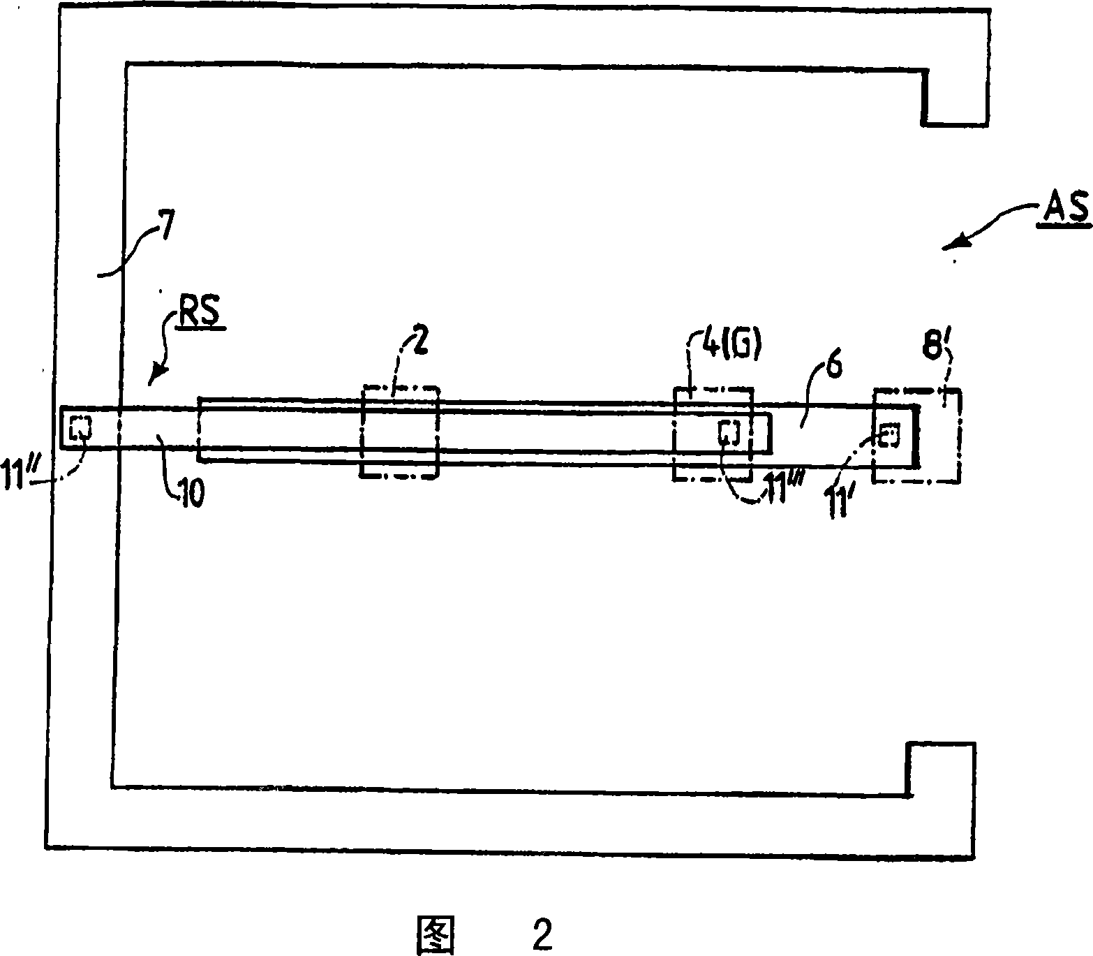
[0038] FIG. 2 shows an antenna structure AS which is located within the antenna configuration 1 according to FIG. 1 . The antenna configuration 1 is a dielectric common antenna and includes a strip-shaped first resonator structure 6 and a U-shaped resonator structure 7 . As already described above, the two structures 6 and 7 ar...


PUM


Abstract

Regarding an antenna configuration (1) preferably provided for a telecommunication device and comprising a first resonator structure (6) and second resonator structure (RS) being capacitive coupled with the first resonator structure (6) it is suggested to provide the antenna configuration (1) with a control electrode (2) and a switching stage (3), said control electrode (2) by means of the switching stage (3) being switchably connected to ground (G) and said switching stage (3) enabling to change capacitive coupling of the two resonator structures (6, RS) and thus to change the resonance frequency of the antenna configuration (1) and making possible to switch between a first frequency range and a second frequency range for enhancing the bandwidth and achieving improved matching of the antenna configuration (1).

Description

technical field [0001] The invention relates to an antenna configuration for a telecommunication device, a power line device comprising the antenna configuration and a method of operating a telecommunication device. Such antenna configurations are used in wireless handheld communication devices such as mobile telephones or data communication cards such as memory cards used in laptop computers and the like. Background technique [0002] In the field of wireless telecommunications, electromagnetic waves in the microwave region are used to transmit information. Therefore, the main component of telecommunication equipment is the antenna configuration, which is able to receive and transmit electromagnetic waves. [0003] Future telecommunications equipment is expected to satisfy both improvements. On the one hand, they are expected to be smaller than today's devices, which also means that their antenna configurations must be reduced in size. On the other hand, expect them to b...

Claims


Application Information

Patent Timeline
Patent Type & Authority Applications(China)
IPC IPC(8): H01Q1/24H01Q9/04H01Q5/00H01Q1/40H01Q1/22H01Q1/42H01Q5/10H01Q21/28
CPCH01Q9/0457H01Q21/28H01Q9/0442H01Q9/145H01Q1/40H01Q1/42H01Q1/22H01Q9/0414H01Q1/243
Inventor H·佩尔泽
Owner NXP BV
Learn More