
Sensor device, retrieval device, and relay device

一种传感设备、中继设备的技术,应用在传输系统、信号传输系统、数字传输系统等方向,能够解决妨碍可量测性的确保、更新间隔不能够增长、处理器负荷增大等问题

Inactive Publication Date: 2007-03-21
PANASONIC INTELLECTUAL PROPERTY CORP OF AMERICA
View PDF2 Cites 2 Cited by
  • Summary
  • Abstract
  • Description
  • Claims
  • Application Information

AI Technical Summary

Problems solved by technology

[0023] Therefore, there is a problem that the update data from each sensor node is concentrated in the range frequency band immediately below the database system, compressing the frequency band, increasing the load on the processor on the database side, and hindering the assurance of scalability.
However, the pressure of the frequency band and the increase of the load have no upper limit with the increase of the number of sensor nodes, so the problem cannot be solved in essence.
Furthermore, due to the dependence on the length of the database update interval, the measured values ​​measured by the sensor will lose real-time performance, so the update interval cannot be increased.
And, of course, with this approach, a new database system must be imported and managed

Method used


Image

  • Sensor device, retrieval device, and relay device
  • Sensor device, retrieval device, and relay device
  • Sensor device, retrieval device, and relay device

Examples


no. 1 Embodiment approach

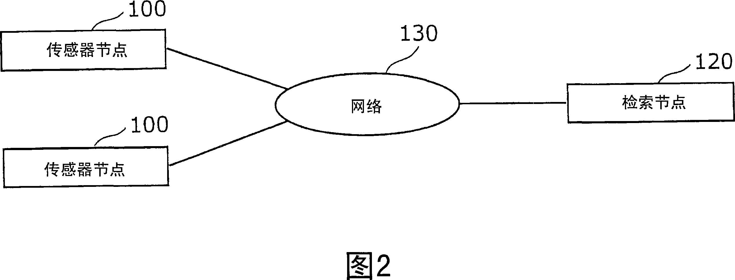
[0075] First, the structures of the sensor node and the search node according to the first embodiment of the present invention will be described in detail using FIGS. 2 to 4 .

[0076] FIG. 2 is a diagram showing an outline of the configuration of the sensor network in the first embodiment of the present invention.

[0077] As shown in FIG. 2 , the sensor network in the first embodiment includes a search node 120 and a plurality of sensor nodes 100 . The sensor node 100 is an example of a sensor device of the present invention, and the search node 120 is an example of a search device of the present invention.

[0078] The search node 120 and the plurality of sensor nodes 100 are connected to the network 130 and can communicate with each other. The network 130 is a network having a plurality of channels for communication.

[0079] Furthermore, in the first to third embodiments described below, a case where the network 130 specifically uses an Internet Protocol version 6 (IPv6...

no. 2 Embodiment approach

[0218] As a second embodiment of the present invention, an example of a sensor network in a physical distribution management system using a wireless tag on which an individual identification number is recorded will be described below. The so-called wireless tag is a tiny wireless IC chip used for object identification, also known as "IC tag", "RF tag" and so on. The identification information of itself is recorded in the wireless tag, and it has the ability to use radio waves to send and receive information with the management system.

[0219] Furthermore, the individual identification number in the wireless tag is, as described above, identification information of a numbering system capable of ensuring the consistency of the identification number within a specific range. For example, EPC used in RFID, etc.

[0220] RFID is a worldwide individual identification number that guarantees uniqueness. In EPC, there is a numbering system management organization for ensuring consist...

no. 3 Embodiment approach

[0252] In the third embodiment of the present invention, a method is described in which crossover search is possible between sensor networks having different network address assignment policies.

[0253] FIG. 14 is a diagram showing an outline of the configuration of a sensor network according to a third embodiment.

[0254] In the sensor network in the third embodiment, the sensor network (SN2) on the IPv6 network 111, the sensor network (SN1) on the P2P network 703, and the sensor network (SN3) on the ad hoc network 708 are respectively connected by the relay node 800. Furthermore, SN1 and SN2 are examples of the first network and the second network in the relay device of the present invention, respectively.

[0255] Furthermore, sensor node 100 and search node 120 described in the first embodiment are connected to SN2, and sensor node 100a and sensor node 100b, which are sensor nodes having the same structure as sensor node 100, are connected to SN1 and SN3, respectively. ...


PUM


Abstract

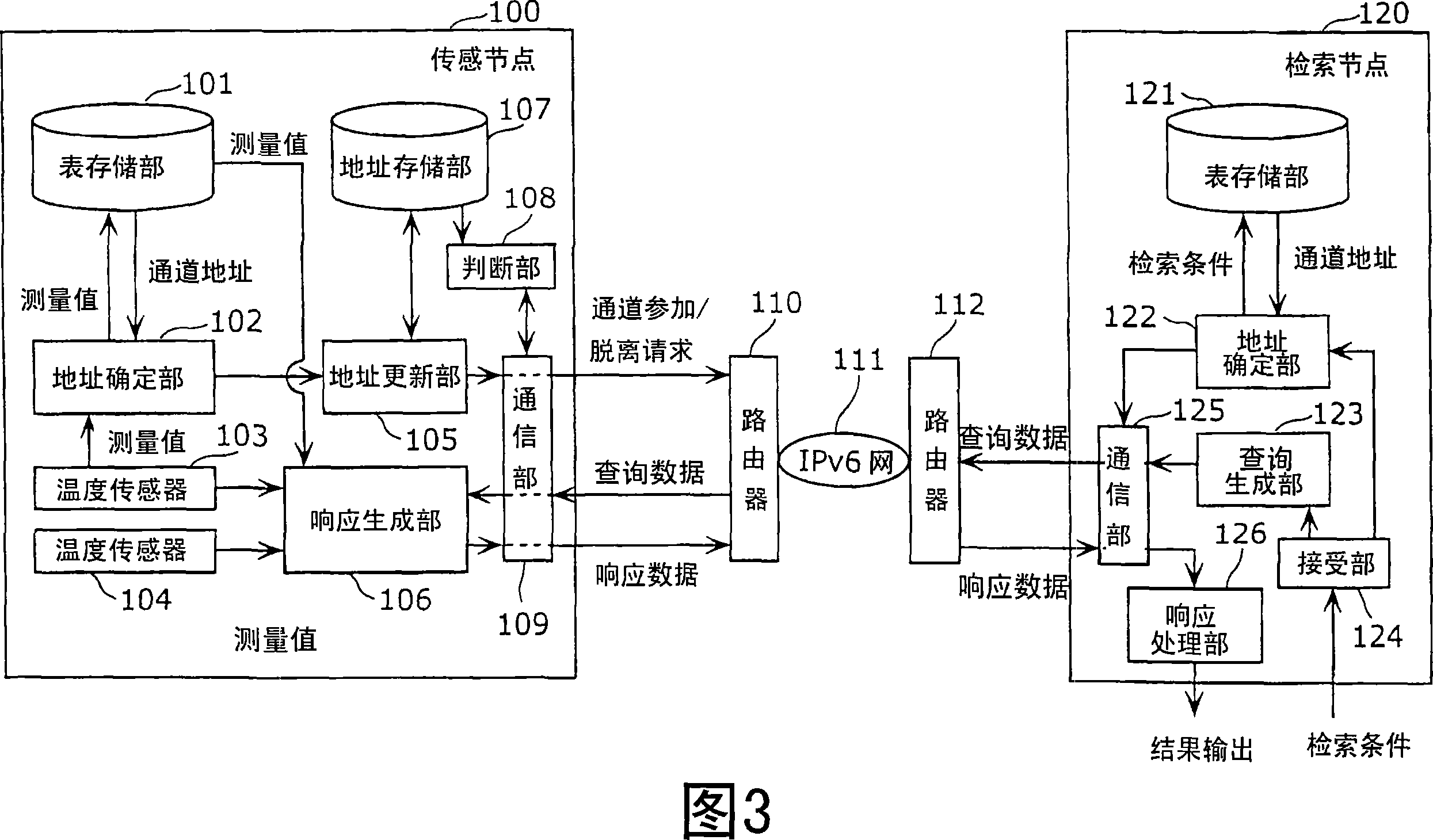
A sensor device is provided to comprise an address storage unit (107) for storing a channel address to be used, a temperature sensor (103), a table storage unit (101) for storing an address table in which a measured value and the channel address are made to correspond to each other, an address specify unit (102) for specifying the channel address corresponding to the measured value obtained from the temperature sensor (103), an address update unit (105) for updating the channel address of the address storage unit (107), a decision unit (108) for deciding whether or not inquiry data is addressed to the channel address stored in the address storage unit (107), a response making unit (106) for making response data responding to the inquiry data in case it is decided that the inquiry data is addressed to the channel address, and a communication unit (109) for sending the response data to a retrieval node (120).

Description

technical field [0001] The present invention relates to a sensing device that measures surrounding conditions, a retrieval device that retrieves the sensing device through a network, and a relay device that relays communication between the sensing device and the retrieval device. Background technique [0002] In the past, there was a sensor network that was used as a network system for observation of natural phenomena such as weather and temperature, situation investigation at the time of a disaster, inventory management, etc. In this sensor network, in order to realize wide-ranging services, an Internet Protocol (IP) network, for example, is used as a backbone device for connecting various components such as sensors and databases. [0003] And, in order to connect the sensors to the network, a sensor node is used, which, as a sensor device, integrates one or more sensors with network communication functions. [0004] In order to make full use of the sensor network, it is n...

Claims


Application Information

Patent Timeline
Patent Type & Authority Applications(China)
IPC IPC(8): G08C15/00H04L12/56G08C17/02
CPCG08C17/00H04W84/18H04W40/246H04W40/20H04L45/16H04W8/26
Inventor 石井友规
Owner PANASONIC INTELLECTUAL PROPERTY CORP OF AMERICA
Learn More