Eureka AIR delivers breakthrough ideas for toughest innovation challenges, trusted by R&D personnel around the world.

Liquid crystal display device

A technology of a liquid crystal display device and a liquid crystal layer, which is applied in nonlinear optics, instruments, optics, etc., can solve the problems of poor color display effect of the display device, and achieve the effect of improving the color display effect and the color mixing effect.

Inactive Publication Date: 2007-03-14
INNOCOM TECH SHENZHEN +1
View PDF0 Cites 6 Cited by
  • Summary
  • Abstract
  • Description
  • Claims
  • Application Information

AI Technical Summary

Problems solved by technology

[0006] In order to solve the problem of poor color display effect of liquid crystal display devices in the prior art, it is necessary to provide a liquid crystal display device with good color display effect

Method used


Image

  • Liquid crystal display device
  • Liquid crystal display device
  • Liquid crystal display device

Examples


Embodiment Construction

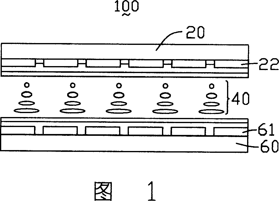
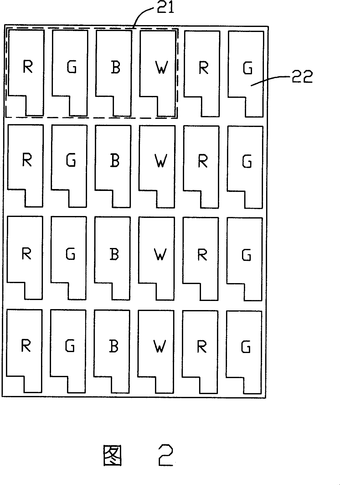
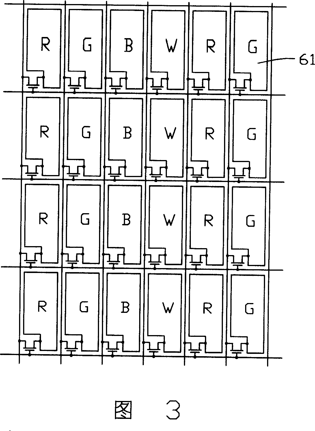
[0023] The first embodiment of the liquid crystal display device of the present invention is shown in FIG. 4, FIG. 5 and FIG. Layer 240. The inner surface of the first substrate 220 has a plurality of color filter units 221. The color filter unit 221 includes four sub-filter units 222. The sub-filter units 222 are curved and arranged side by side. They are red respectively. A sub-filter unit (R), a green sub-filter unit (G), a blue sub-filter unit (B) and a white sub-filter unit (W). The inner surface of the second substrate 260 has a plurality of pixel electrodes 261 in an arc-shaped curved structure. The pixel electrodes 261 are arranged corresponding to the sub-filter unit 222 and have the same bending direction as the sub-filter unit 222 . The pixel electrode 261 is made of conductive material, such as transparent conductive material indium tin oxide or indium zinc oxide.

[0024] Since the color filter unit 221 has an arc-shaped curved structure, the contact sides of tw...


PUM


Abstract

The related LCD comprises a first / second substrate, a LC layer between substrates, and multiple color filter units every with some bending sub-filter units. This invention has better display effect.

Description

【Technical field】 [0001] The invention relates to a liquid crystal display device. 【Background technique】 [0002] Liquid crystal display devices have the characteristics of thinness, low power consumption and less radiation, so they are widely used in the fields of monitors, LCD TVs, mobile phones and portable computers, and become the mainstream of displays, but at the same time, their display brightness and color display The effect puts forward higher requirements. [0003] Generally speaking, a liquid crystal display device uses three primary colors of red (R), green (G) and blue (B) to display images. However, the liquid crystal itself does not emit light, and the backlight module needs to provide a light source for it to display. Due to the limited brightness of the light source provided by the backlight module, and the light loss due to polarizers and color filters in the optical path of the liquid crystal display device is serious. , so the display brightness of th...

Claims


Application Information

Patent Timeline
Patent Type & Authority Applications(China)
IPC IPC(8): G02F1/1335G02F1/1343
Inventor 杨秋莲彭家鹏
Owner INNOCOM TECH SHENZHEN
Why Eureka
Eureka Blog
Learn More