
Engine for portable generator

A generator and engine technology, applied in the direction of machines/engines, engine components, valve devices, etc., can solve the problems of large crankcase volume and unfavorable heat dissipation of the cylinder head, and achieve the effects of heat dissipation, weight reduction, and length shortening

Inactive Publication Date: 2007-03-14
陈维加
View PDF0 Cites 6 Cited by
  • Summary
  • Abstract
  • Description
  • Claims
  • Application Information

AI Technical Summary

Problems solved by technology

[0003] 1. Since two cams are arranged on one camshaft, the length of the camshaft is relatively long, resulting in a relatively large volume of the crankcase, which is extremely unfavorable for portable generators
[0004] 2. Since the camshaft is set parallel to the crankshaft, and the two cams are located on one camshaft, the connection line between the two valves must also be parallel to the camshaft, and the cooling air in the unit is also parallel to the crankshaft and the camshaft Therefore, the cooling air goes along the line between the two valves, which is extremely unfavorable for the heat dissipation of the cylinder head

Method used


Image

  • Engine for portable generator
  • Engine for portable generator
  • Engine for portable generator

Examples


Embodiment

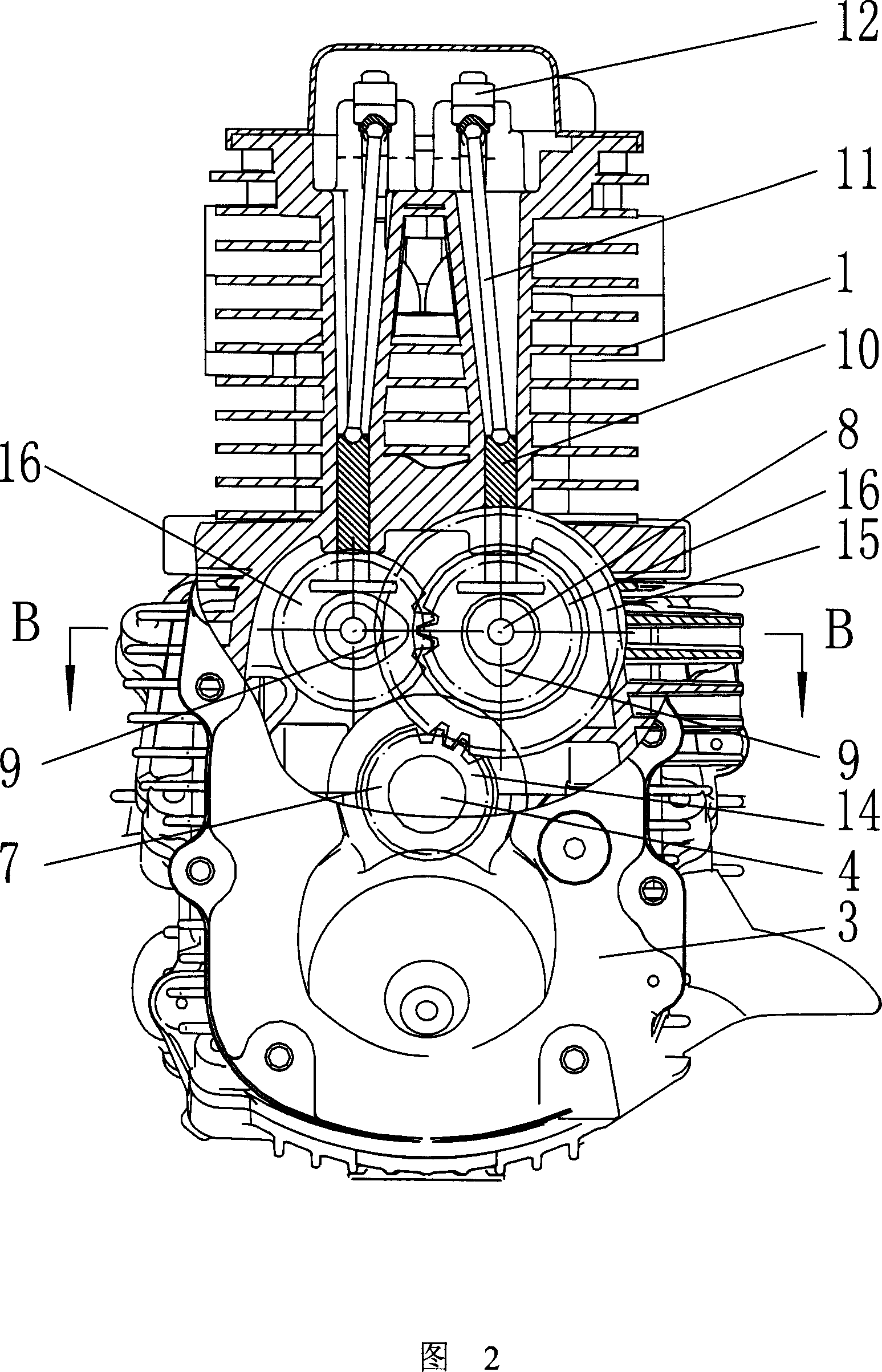
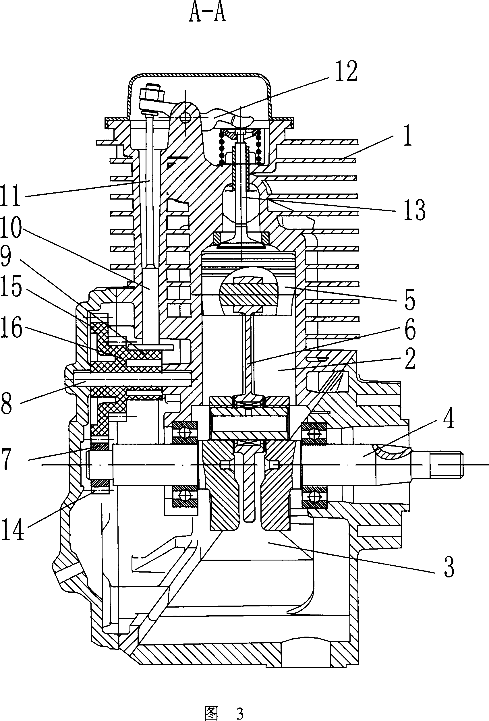
[0018] Embodiment: as shown in Fig. 1, Fig. 2, Fig. 3, Fig. 4, a kind of engine device of portable generator, comprises cylinder 2 in cylinder head 1 and crankshaft 4 in crankcase 3, in cylinder 2 The piston 5 drives the crankshaft 4 through the connecting rod 6, and the crankshaft 4 drives the camshaft 8 through the gear 7. There are two camshafts 8, and the two camshafts 8 are arranged side by side and parallel to the crankshaft 4 respectively. Cam 9, the two cams 9 are located in the same plane, and the plane is perpendicular to the crankshaft 4 and the camshaft 8, the cam 9 touches the tappet 10, the tappet 10 touches the push rod 11, and the push rod 11 controls the valve through the rocker arm 12 13 switch, the line between the two valves 13 is perpendicular to crankshaft 4 and camshaft 8.

[0019] A driving gear 14 is fixed on the crankshaft 4, and the driving gear 14 meshes with a driven gear 15 fixed on one of the camshafts 8, and two camshafts 8 are respectively fixe...


PUM


Abstract

The invention discloses a portable engine installation of electric generator, comprising air cylinder in head and crankshaft in box. The piston in cylinder drives crankshaft, which drives cam shaft through gear, through connector. The cam on cam shaft drives tapper arm, which drives pushing bar. The pushing bar controls switch of air gate through swing arm. There are two paralleling said cam shafts, which are parallel to crankshaft respectively. One cam is set on each cam shaft. Previous mechanism can not only reduce the cubage of crankshaft box but also accelerate heating of cylinder head dispersed.

Description

technical field [0001] The invention relates to an engine device of a portable generator. Background technique [0002] Portable generators currently on the market include an engine and a generator driven by the engine, both of which can be installed in a sound-proof box body with a carrying handle on the top, so as to be convenient for users to carry. A traditional engine includes an upper cylinder head cylinder and a lower crankcase. The cylinder head is provided with a cylinder, and the upper end of the cylinder is provided with an intake valve and an exhaust valve. The piston in the cylinder drives the crankshaft located below through the connecting rod. Drive the generator to generate electricity. At the same time, the crankshaft also drives the camshaft parallel to it through the gear. There are two cams on the camshaft. The two cams touch the upper tappet respectively, and the tappet touches the upper push rod. The rod drives the valve switch through the rocker arm. ...

Claims


Application Information

Patent Timeline
Patent Type & Authority Applications(China)
IPC IPC(8): F01L1/047
Inventor 陈维加
Owner 陈维加
Learn More