
Eccentric wheel rotary engine

A technology of rotating engines and eccentric wheels, applied to combustion engines, machines/engines, internal combustion piston engines, etc., can solve problems such as complex ignition and control methods, low efficiency of reciprocating engines, incomplete fuel combustion, etc., to achieve good combustion performance, Reduce the conversion and transfer process, and facilitate the promotion and use of the effect

Inactive Publication Date: 2007-02-28
SOUTHWEST JIAOTONG UNIV
View PDF0 Cites 3 Cited by
  • Summary
  • Abstract
  • Description
  • Claims
  • Application Information

AI Technical Summary

Problems solved by technology

The ignition mode of reciprocating engine can be compression ignition type or ignition type, and can use a variety of fuels; however, the efficiency of reciprocating engine is low, and the bottleneck restricting the development of reciprocating engine to high speed is the reciprocating speed of piston. Inertial force, the current average piston speed is up to 14.64 m / s
The existing rotary engine has a complex structure and higher efficiency than the reciprocating engine, but the three vertices of the triangular rotor are in line contact with the cylinder profile, the seal is not good, the gas leakage is large at low speed, and the performance is poor; and the rotary engine At present, ignition ignition is basically used, and the best fuel is gasoline. If diesel is used, complex ignition and control methods are required.
The existing two types of engines all use a gear mechanism, and the reciprocating engine also needs a crankshaft connecting rod mechanism to realize the rotation of the output shaft, and its structure is complicated.
In addition, both types of engines have overlapping phenomenon of intake and exhaust, so that the intake is insufficient, the exhaust is not clean, and the fuel combustion is not complete.

Method used


Image

  • Eccentric wheel rotary engine
  • Eccentric wheel rotary engine
  • Eccentric wheel rotary engine

Examples


Embodiment

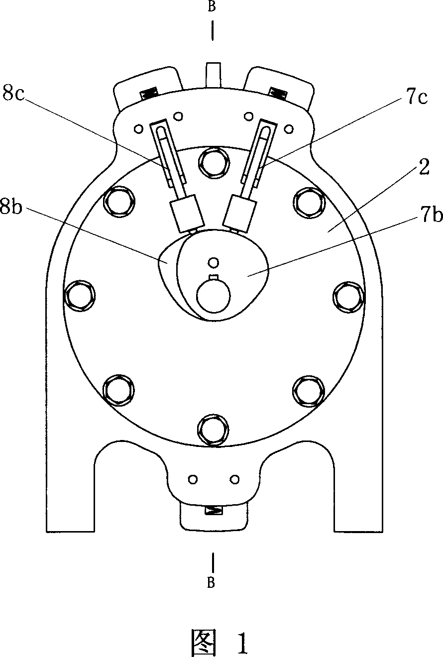
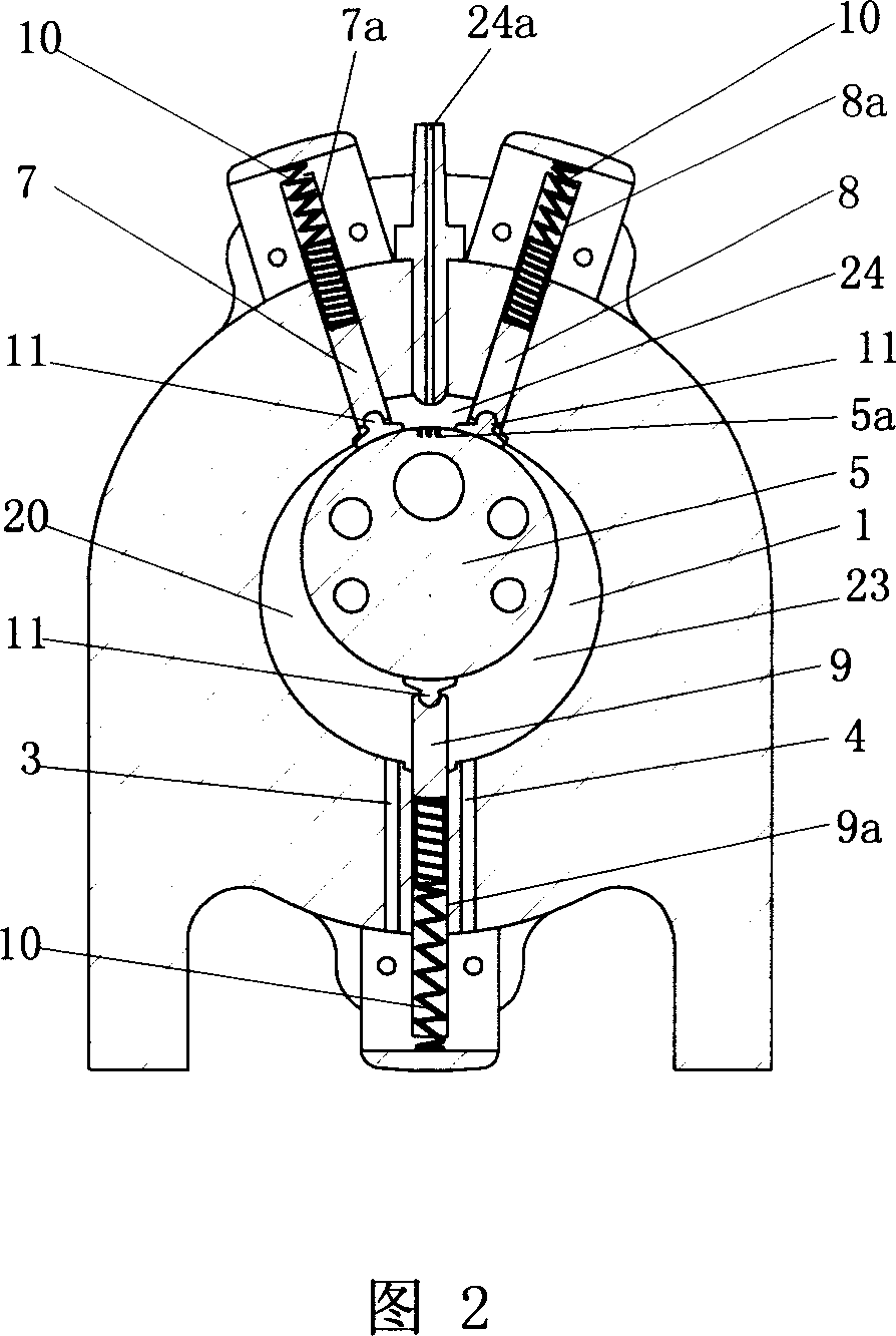
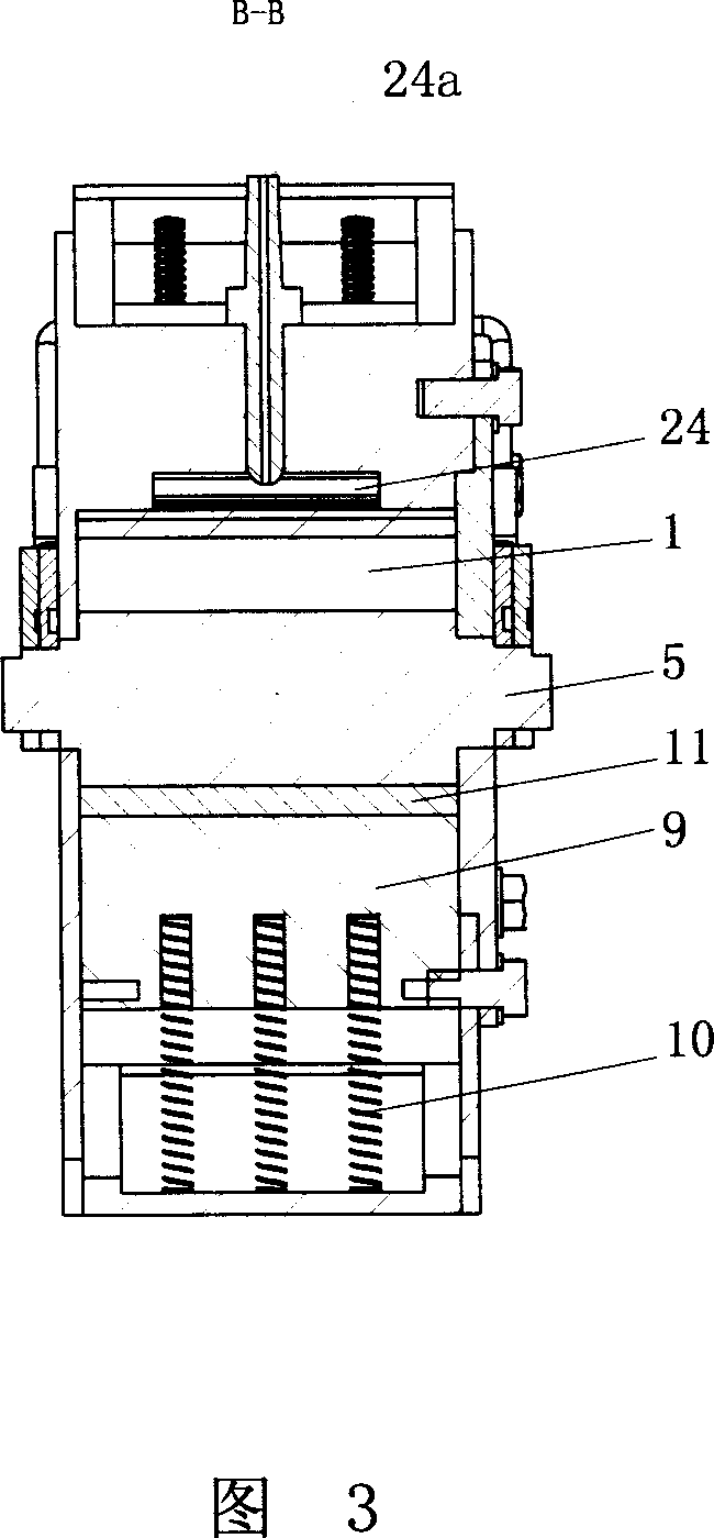
[0043] Figures 1-5 show that a specific embodiment of the present invention is: an eccentric wheel rotary engine, comprising a cylinder 1 with a cylindrical cavity, a cylinder head 2, an air inlet 3, and an exhaust port 4. The cylinder 1 is provided with an eccentric wheel 5 inscribed with the cavity of the cylinder 1, the rotation axis of the eccentric wheel 5 coincides with the center line of the cavity of the cylinder 1, and there is a shallow basin-shaped combustion chamber 24 on the wall of the cylinder 1. The combustion chamber 24 has an oil injection hole 24a connected with the injector.

[0044] The walls of the cylinder 1 on both sides of the combustion chamber 24 are respectively provided with a main baffle chute 7a and an auxiliary baffle chute 8a, and the wall of the cylinder 1 opposite to the combustion chamber 24 is provided with a partition chute 9a; The main baffle plate 7, the secondary baffle plate 8 and the partition plate 9 are fitted in the slot 7a, the se...


PUM


Abstract

The invention relates to an eccentric rotational engine, which is formed by cylinder, eccentric wheel tangent with the cylinder, main baffle plate and auxiliary baffle plate on the cylinder wall and controlled by cam, a baffle plate controlled by spring, and a concave burning room on the cylinder wall, wherein the eccentric wheel rotates around the center of cylinder, to form one movable arc chamber with the inner chamber of cylinder; when working, the main baffle plate, the auxiliary baffle plate, and the baffle plate will separate the arc chamber into the gas inlet room, compress room, expansion room and discharge room which will periodically enlarge and reduce; the burning room is periodically connected to the compress room or expansion room, to compress and drive gas via eccentric wheel, and function the eccentric wheel at its back via burning gas. The invention has simple structure, better sealing effect, and high efficiency.

Description

technical field [0001] The present invention relates to an engine, in particular to a rotary engine. Background technique [0002] Reciprocating engines and rotary engines are two major types of engines. The ignition mode of reciprocating engine can be compression ignition type or ignition type, and can use a variety of fuels; but the efficiency of reciprocating engine is low, and the bottleneck restricting the development of reciprocating engine to high speed is the reciprocating speed of piston. Inertial force, the current average piston speed is up to 14.64 m / s. The existing rotary engine has a complex structure and higher efficiency than the reciprocating engine, but the three vertex angles of the triangular rotor are in line contact with the cylinder profile, the seal is not good, the gas leakage is large at low speed, and the performance is poor; and the rotary engine At present, ignition type ignition is basically used, and the best fuel is gasoline. If diesel oil i...

Claims


Application Information

Patent Timeline
Patent Type & Authority Applications(China)
IPC IPC(8): F02B53/02F02B55/02F02B55/14F02B53/10F02B55/08F02B55/16
CPCY02T10/17Y02T10/12
Inventor 史炎
Owner SOUTHWEST JIAOTONG UNIV
Learn More