Hydraulic pressure oxygenate apparatus
A water pressure and water tank technology, applied in water aeration, water/sludge/sewage treatment, climate change adaptation, etc., can solve problems such as large energy consumption
- Summary
- Abstract
- Description
- Claims
- Application Information
AI Technical Summary
Problems solved by technology
Method used
Image
Examples
specific Embodiment approach 1
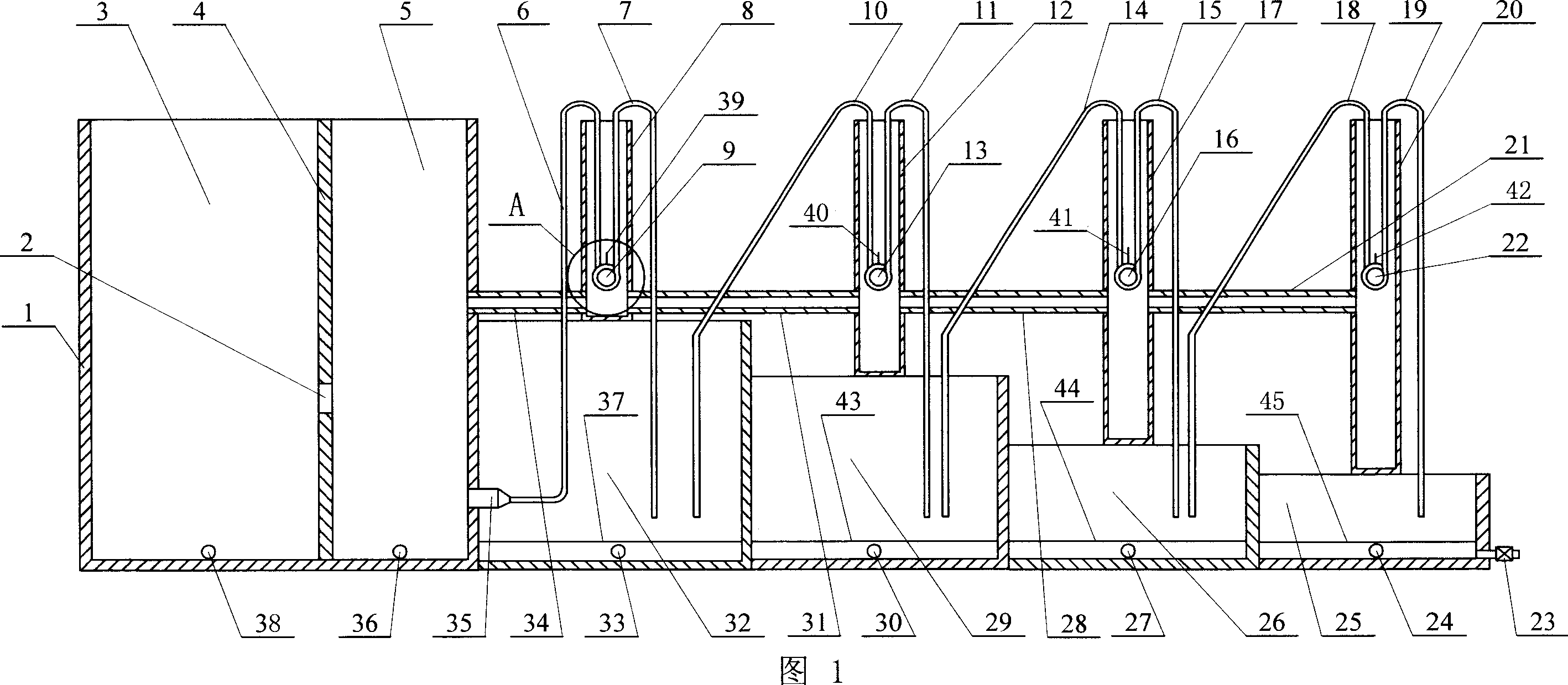
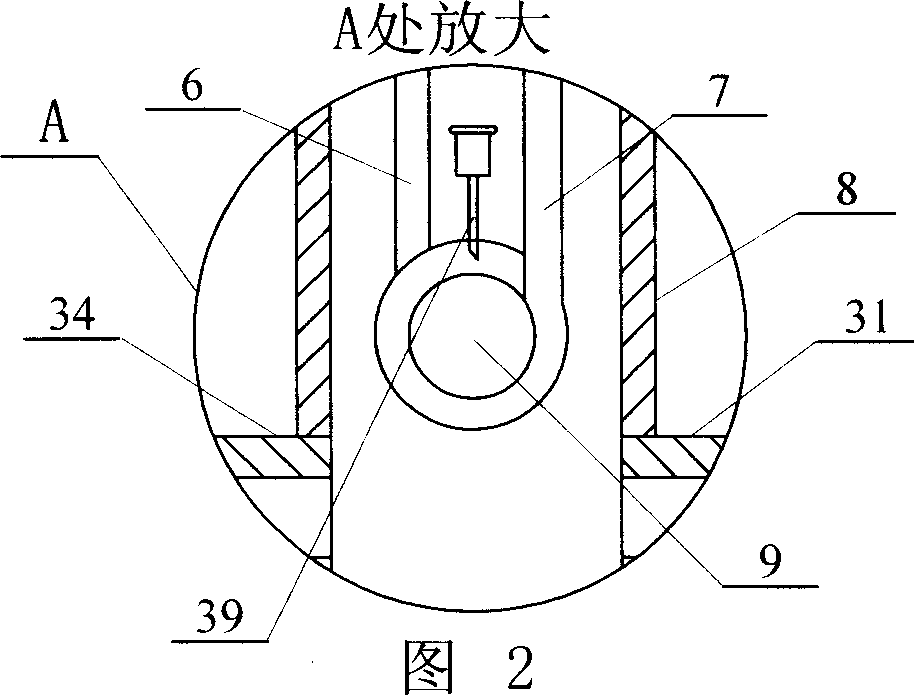
[0005] Specific embodiment one: (referring to Fig. 1, Fig. 2) present embodiment is made up of water storage tank 1, the first fish pond 32 and the first oxygenation unit, water storage tank 1 and the first fish pond 32 are fixedly connected, The height of the first fish pond 32 is lower than the height of the water storage tank 1, an outlet pipe 35 is provided between the water storage tank 1 and the first fish pond 32, and the first oxygenation unit consists of the first connecting pipe 34, the first Inlet pipe 6, the first float 9, the first outlet pipe 7, the first float water tank 8 and the first air intake pipe 39 form, the first float water tank 8 is fixed on the top of the first fish pond 32, the first float water tank 8 and The first connecting pipe 34 is fixedly connected between the water storage tanks 1, and the two ends of the first connecting pipe 34 communicate with the first float water tank 8 and the water storage tank 1 respectively. The outlet end of the fir...
specific Embodiment approach 2
[0006] Specific embodiment two: (referring to Fig. 1) in the water storage tank 1 of present embodiment, additionally be provided with dividing plate 4, have water hole 2 on the dividing plate 4, the left side of dividing plate 4 forms precipitation area 3, dividing plate 4 Form the clear water area 5 on the right side, the water storage tank 1 on the sedimentation area 3 lower sides is provided with a sewage outlet 38, and the water storage tank 1 on the clear water area 5 lower sides is provided with a sewage outlet 36. Other compositions and connections are the same as in the first embodiment. The water pumped to the water storage tank by the water pump first enters the sedimentation area for sedimentation, and the clear water enters the clear water area through the water hole, so that the water that finally enters the fish pond is clear and transparent, and the sediment in the sedimentation area and the clear water area in the water storage tank is discharged through sewage...
specific Embodiment approach 3
[0007] Specific embodiment three: (referring to Fig. 1) the downside of the first aquarium 32 of the present embodiment is provided with sewage outlet 33, and the first screen cloth 37 is fixed in the first aquarium 32 on the upper side of sewage outlet 33. Other compositions and connections are the same as in the first embodiment.
PUM
 Abstract
Description
Claims
Application Information
 - R&D
- Intellectual Property
- Life Sciences
- Materials
- Tech Scout
- Unparalleled Data Quality
- Higher Quality Content
- 60% Fewer Hallucinations
Browse by: Latest US Patents, China's latest patents, Technical Efficacy Thesaurus, Application Domain, Technology Topic, Popular Technical Reports.
© 2025 PatSnap. All rights reserved.Legal|Privacy policy|Modern Slavery Act Transparency Statement|Sitemap|About US| Contact US: help@patsnap.com


