Method and device for measuring angular oscillation through laser interference
A technology of laser interference and measuring device, which is applied in the direction of measuring device, measuring ultrasonic/sonic/infrasonic wave, instruments, etc.
- Summary
- Abstract
- Description
- Claims
- Application Information
AI Technical Summary
Problems solved by technology
Method used
Image
Examples
Embodiment 1
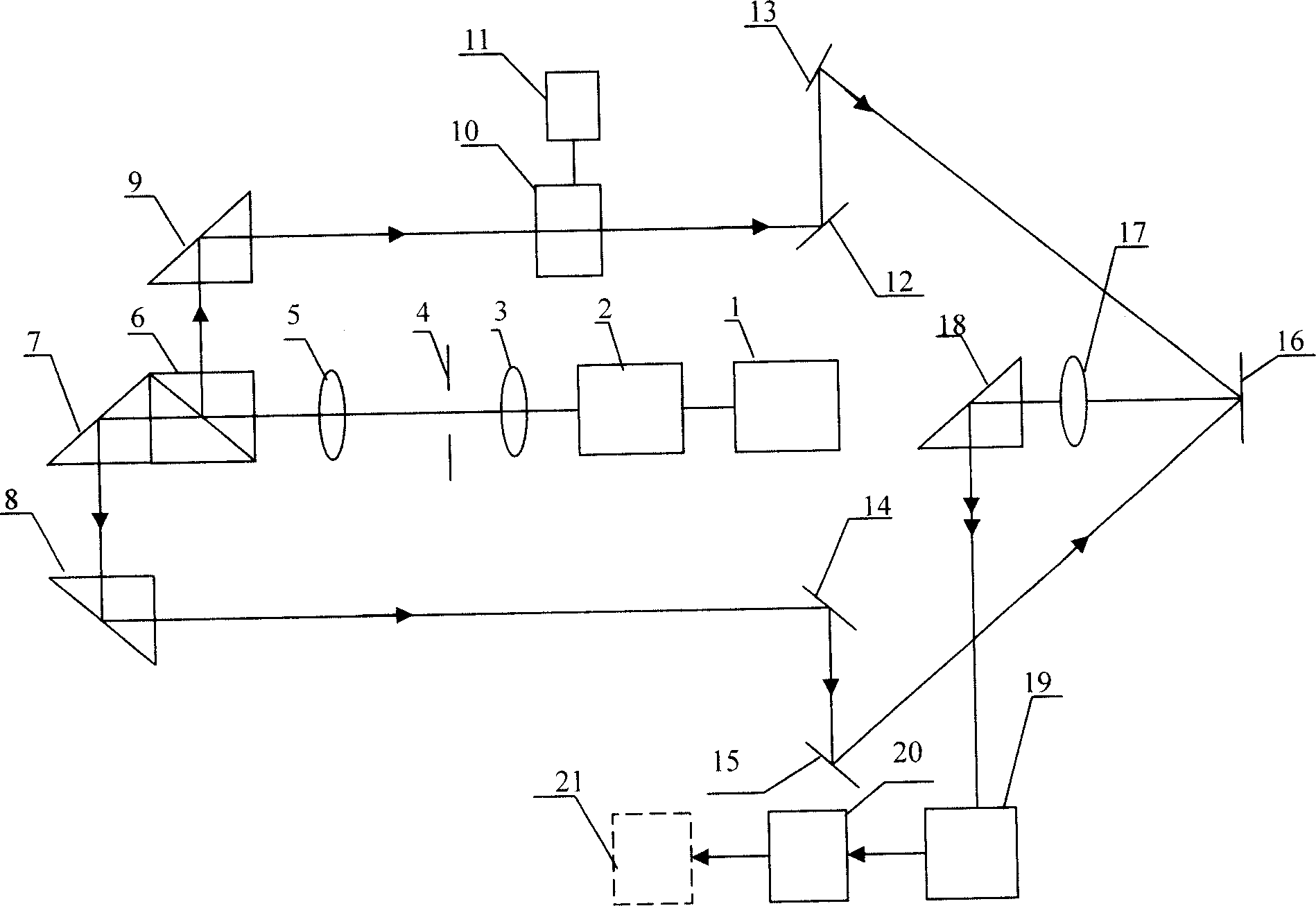
[0017] The angular vibration laser interferometry device includes a laser power supply 1, a laser 2, a lens 3, an aperture 4, a lens 5, a parallel beam splitting unit 6, an acousto-optic modulator power supply 10, an acousto-optic modulator 11, and plane mirrors 12, 13, 14 , 15, grating 16, receiving lens 17, reflective plane mirror 18, photoelectric conversion device 19, electrical frequency mixing down-conversion processing unit 20 and data acquisition and processing unit 21, laser power supply is connected with laser, the light that laser sends passes through lens 3, light After the aperture 4 reaches the lens 5, one path of light after passing through the parallel beam splitting unit 6 passes through the acousto-optic modulator 10, and then enters the grating 16 through the plane mirror group 12, 13, and the other path of light enters the grating 16 through the mirrors 14, 15, The coincident light beam of the two diffracted lights passing through the receiving lens 17 reach...
Embodiment 2
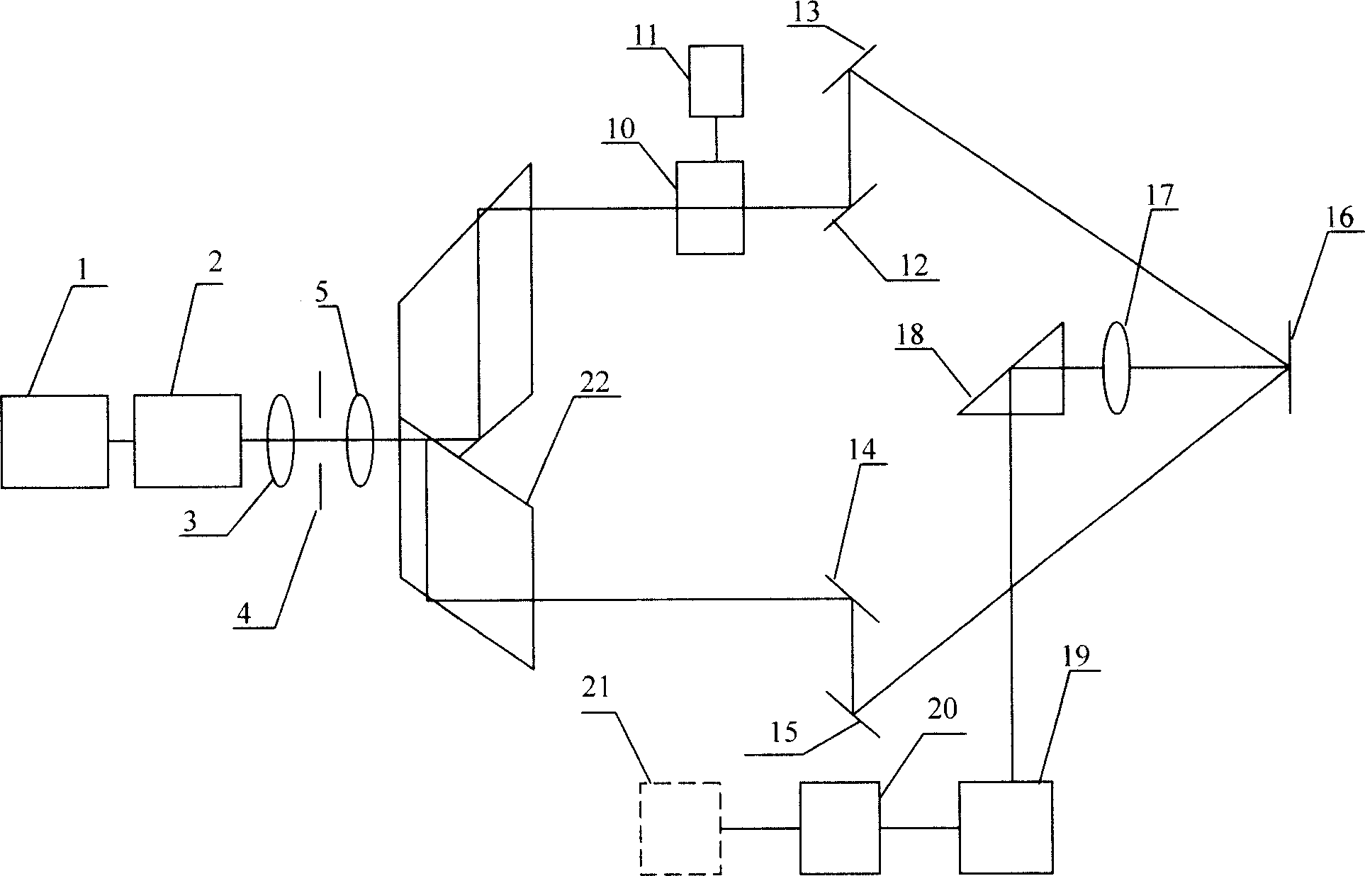
[0022] The angular vibration laser interferometry device includes a laser power supply 1, a laser 2, a lens 3, an aperture 4, a lens 5, a parallel beam splitting unit 22, an acousto-optic modulator power supply 10, an acousto-optic modulator 11, and plane mirrors 12, 13, 14 , 15, grating 16, receiving lens 17, reflective plane mirror 18, photoelectric conversion device 19, electrical frequency mixing down-conversion processing unit 20 and data acquisition and processing unit 21, laser power supply is connected with laser, the light that laser sends passes through lens 3, light After the diaphragm 4 reaches the lens 5, one path of light after passing through the parallel beam splitting unit 22 passes through the acousto-optic modulator 10, and then enters the grating 16 through the plane reflector group 12, 13, and the other path of light enters the grating 16 through the reflectors 14, 15, The coincident light beam of the two diffracted lights passing through the receiving lens...
PUM
 Abstract
Description
Claims
Application Information
 - R&D Engineer
- R&D Manager
- IP Professional
- Industry Leading Data Capabilities
- Powerful AI technology
- Patent DNA Extraction
Browse by: Latest US Patents, China's latest patents, Technical Efficacy Thesaurus, Application Domain, Technology Topic, Popular Technical Reports.
© 2024 PatSnap. All rights reserved.Legal|Privacy policy|Modern Slavery Act Transparency Statement|Sitemap|About US| Contact US: help@patsnap.com


