Rake reception device and rake reception method

A technology for receiving devices and pointers, applied in electrical components, transmission systems, etc., to solve problems such as inability to allocate pointers

Inactive Publication Date: 2007-02-14
PANASONIC CORP
View PDF1 Cites 0 Cited by
  • Summary
  • Abstract
  • Description
  • Claims
  • Application Information

AI Technical Summary

Problems solved by technology

Therefore, a RAKE receiver installed in a conventional CDMA receiver has a problem that it cannot assign an appropriate number of pointers to a channel according to the communication status
In other words, if the number of RAKE receivers (K) is increased in order to receive more channels, the number of pointers (K×N) in the CDMA receiving device will increase, so there will be many pointers in the CDMA receiving device. problem with unused pointers

Method used


Image

  • Rake reception device and rake reception method
  • Rake reception device and rake reception method
  • Rake reception device and rake reception method

Examples


Embodiment Construction

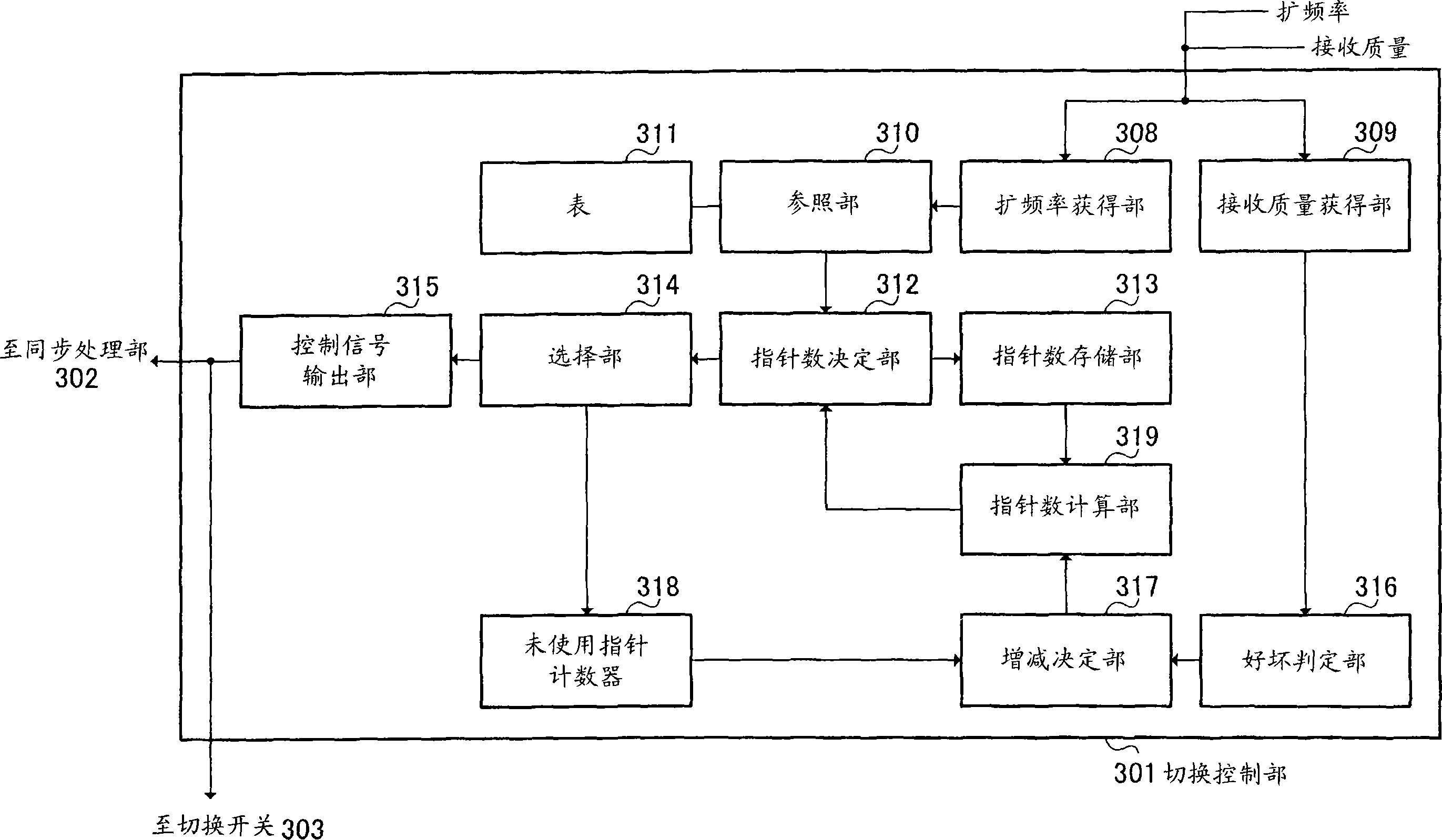
[0015] The gist of the present invention is to make the number of pointers allocated to a channel to be received variable according to its communication state.

[0016] Embodiments of the present invention will be described in detail below with reference to the drawings.

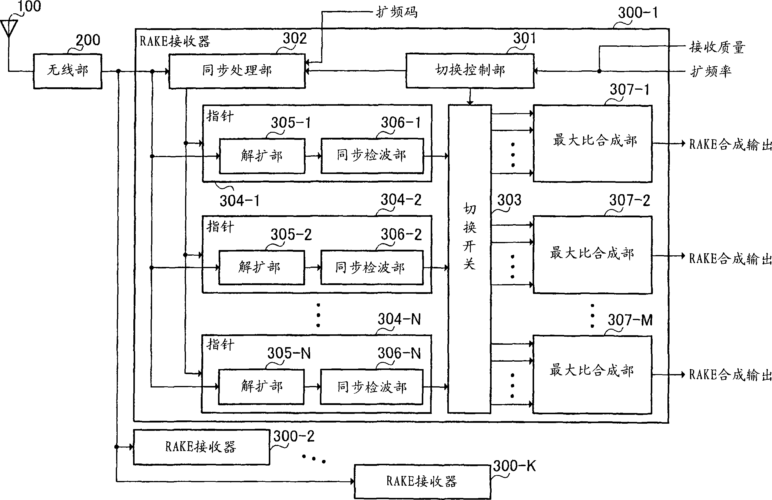
[0017] figure 2 It is a block diagram showing the configuration of a CDMA receiving apparatus according to an embodiment of the present invention.

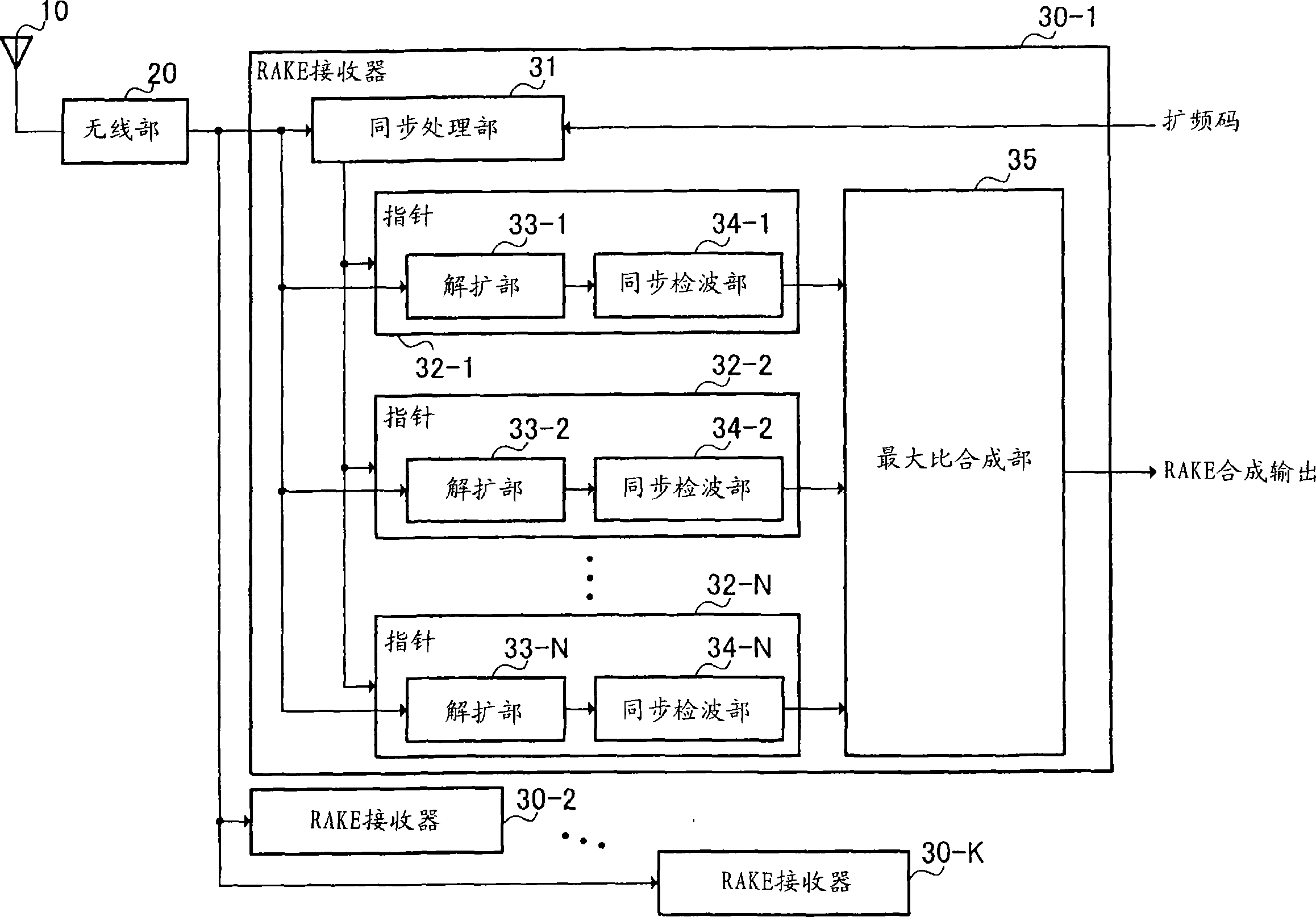
[0018] figure 2 The shown CDMA receiving device consists of an antenna 100, a wireless unit 200 for down-converting an RF signal received by the antenna 100 through a certain channel into a baseband signal (received signal), and a plurality (for example, K) of RAKEs for RAKE reception of the received signal. Receivers 300-1, 300-2, . . . , 300-K are configured. However, the RAKE receivers 300-1, 300-2, . . . , 300-K all have the same structure, so any RAKE receiver will be simply represented as "300" below.

[0019] The RAKE receiver 300 includes: a switch...


PUM


Abstract

A rake reception device capable of allocating an appropriate number of fingers to a channel. In this device, a selection control section sets a finger allocated to the channel from the channel communication state and a control signal based on this setting is output to a synchronization processing section and to a selection switch. According to the control signal, the synchronization processing section detects a path and a spread code phase in a reception signal and allocates the detected path to the finger which has been set. The finger which has been set de-spreads the signal of the path allocated and performs synchronous detection. According to the control signal, the selection switch switches the connection between the finger and a maximum ratio combination section so that the output from the finger is output to the maximum ratio combination section.

Description

technical field [0001] The invention relates to a RAKE receiving device and a RAKE receiving method. Background technique [0002] The CDMA receiving device is used in mobile communication systems such as automobile phones and mobile phones, and adopts CDMA (Code Division Multiple Access) as a wireless access method. In such a CDMA receiver, a channel on a wireless line is identified by a spreading code. Generally, a base station having such a CDMA receiving apparatus performs RAKE reception in which a radio signal transmitted from a mobile station is received as a plurality of propagation paths and combined. [0003] figure 1 is a block diagram showing an example of the structure of a conventional CDMA receiver. exist figure 1 Among them, the antenna 10 receives the RF (Radio Frequency, radio frequency) signal sent from the transmitting end through a certain channel, and after the wireless unit 20 down-converts it into a baseband signal (received signal), multiple (for ...

Claims


Application Information

Patent Timeline
Patent Type & Authority Applications(China)
IPC IPC(8): H04B1/707
CPCH04B2201/70703H04B1/7117H04B2201/7071
Inventor 佐藤崇昭
Owner PANASONIC CORP
Why Eureka
Try Eureka