Actuator

A driver and driven technology, applied in the field of drives, can solve the problems of the moving distance, moving speed, insufficient thrust, and large weight of the driven components, and achieve the effect of miniaturization of the device and stable drive control.

Inactive Publication Date: 2010-11-03
FUJI PHOTO OPTICAL CO LTD
View PDF3 Cites 0 Cited by
  • Summary
  • Abstract
  • Description
  • Claims
  • Application Information

AI Technical Summary

Problems solved by technology

[0006] However, in this method, if the weight of the hammer is small, the moving distance, moving speed, and thrust of the driven member are insufficient, so it is necessary to use a heavy hammer, which has a problem of increasing the size of the device.
In particular, when moving a driven part such as a zoom lens that has a large moving distance, it is necessary to use a very heavy hammer, resulting in a problem of increasing the size of the device.

Method used


Image

  • Actuator
  • Actuator
  • Actuator

Examples


Embodiment Construction

[0026] Hereinafter, preferred embodiments of the actuator of the present invention will be described in detail with reference to the drawings.

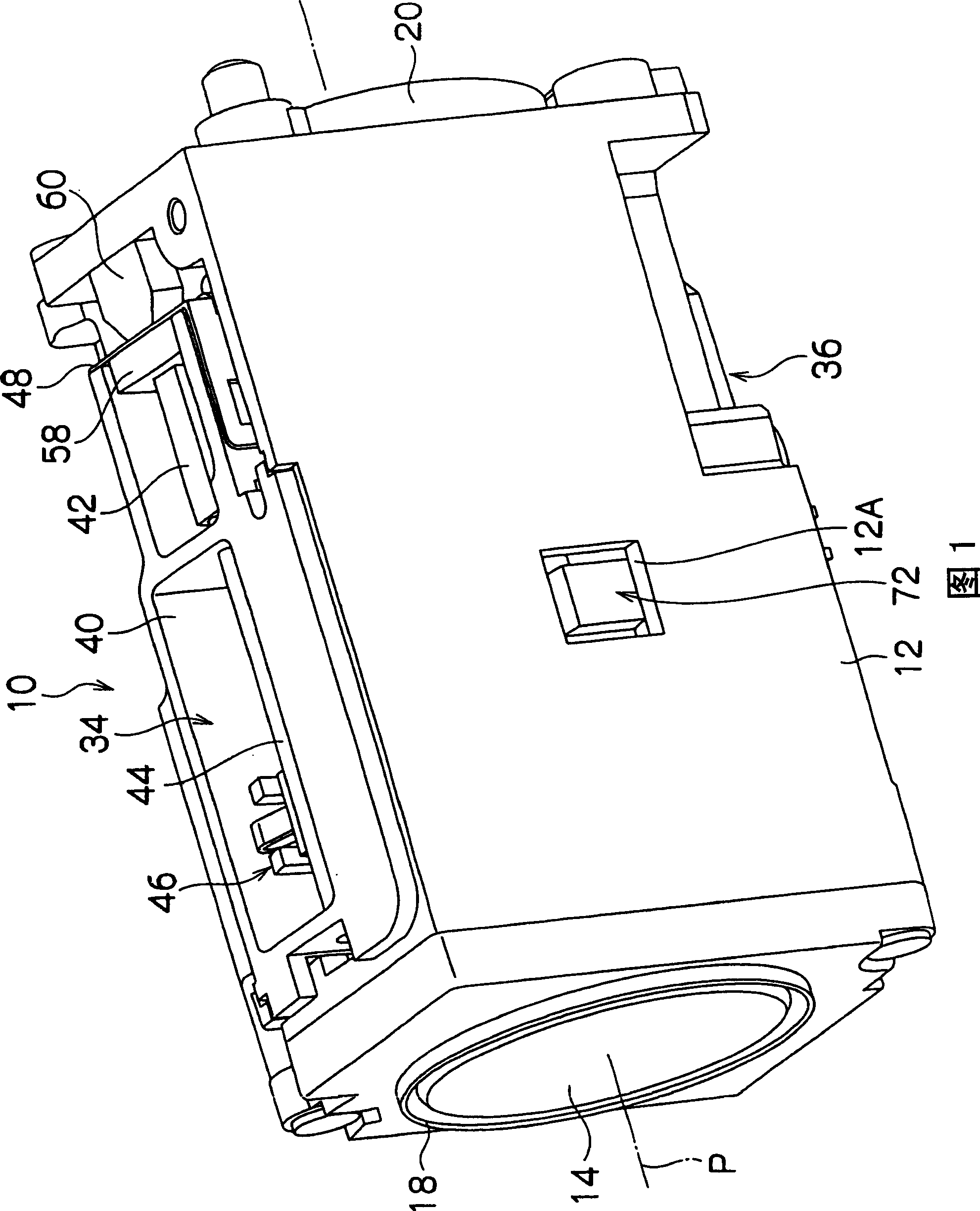
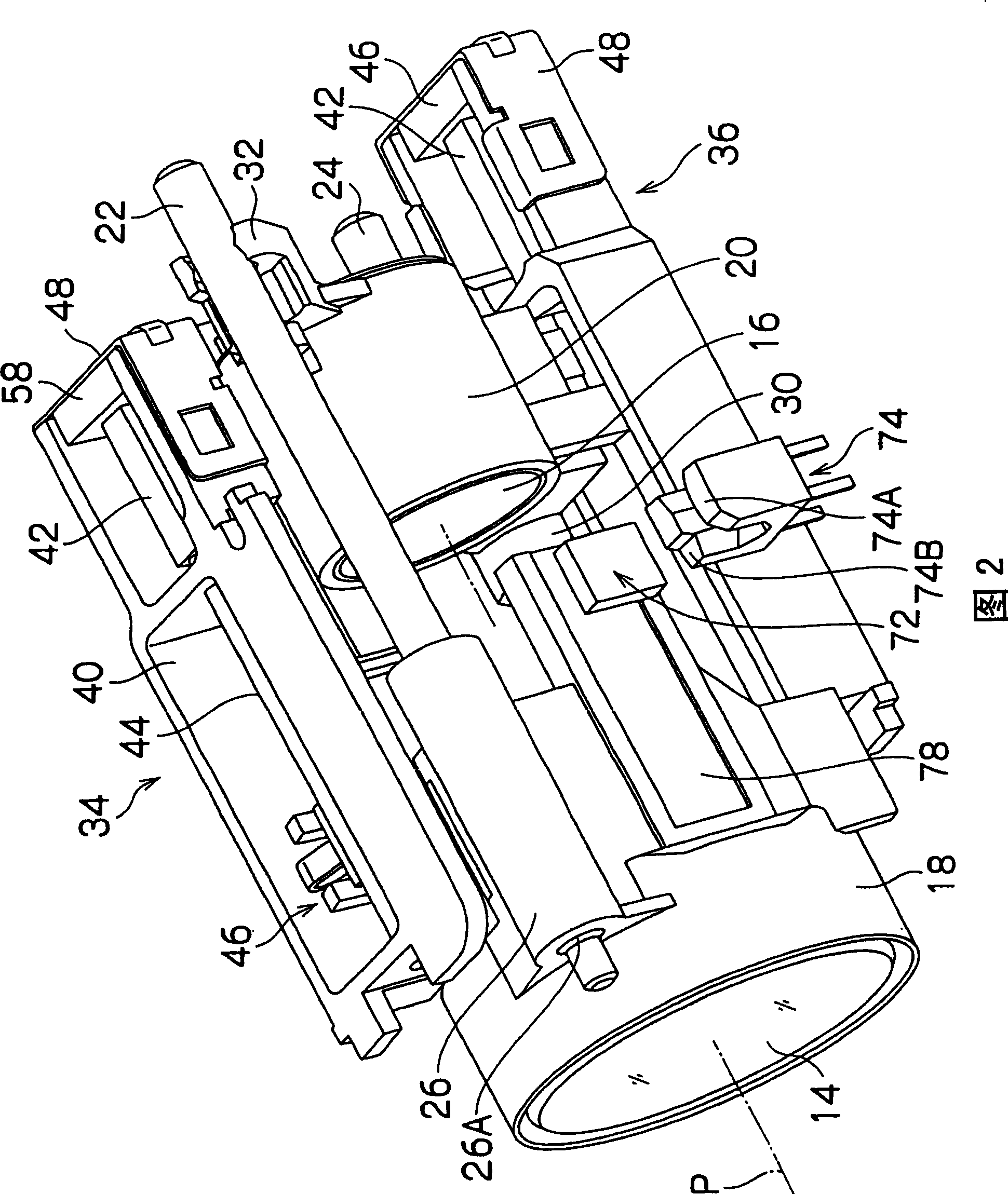
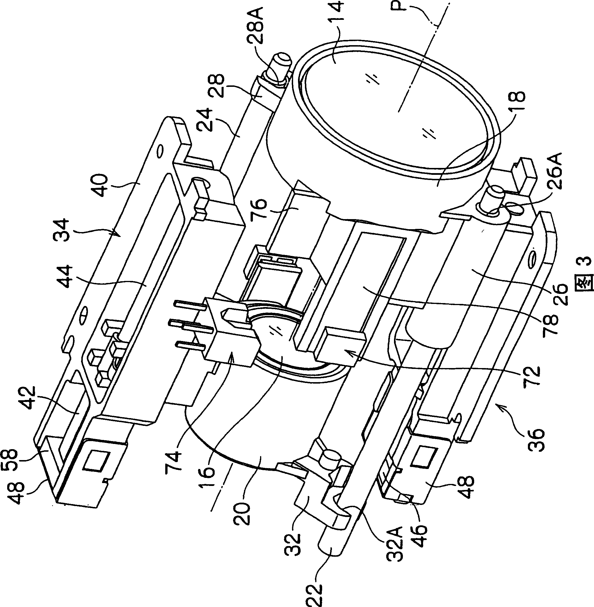
[0027] figure 1 is a perspective view showing a lens device 10 to which an actuator of the present invention is applied, figure 2 , image 3 It is a perspective view showing its internal structure.

[0028] Such as figure 1 As shown, the lens device 10 has a main body 12 formed in a substantially rectangular shape, and the inside of the main body 12 is equipped with figure 2 , image 3 Zoom lens (sets) 14, 16 are shown. Zoom lens (group) 14,16, one side is variable power lens, and the other side is correction lens. In addition, the zoom lenses (groups) 14 and 16 are respectively held by holding frames 18 and 20 , and the holding frames 18 and 20 are slidably supported in the direction of the optical axis P by two guide shafts 22 and 24 . The two guide shafts 22 and 24 are arranged at diagonal positions inside the main body 12...


PUM


Abstract

The invention provides an actuator performing stabilized drive control by supporting the rear end face of a piezoelectric element by means of an elastic supporting member and sustaining the elastic supporting member in elastically deformed state, and capable of miniaturization. The actuator 34 comprising a fixed frame 40, a piezoelectric element 42, a drive shaft 44 fixed to the end face 42A of the piezoelectric element 42, and a driven member 46 engaging with the drive shaft 44 is further provided with a metal fixture 48 fixed to the end face 42B of the piezoelectric element 42 and supporting the end face 42B displaceably for the fixed frame 40, and a member 60 for pressing the metal fixure 48 and holding it in elastically deformed state.

Description

technical field [0001] The present invention relates to a driver, and more particularly relates to a driver mounted in a small precision device such as a digital camera or a mobile phone to drive a zoom lens. Background technique [0002] As a driving device for a lens unit of a digital camera or the like, there is a driver using a piezoelectric element. For example, in the actuator of Patent Document 1, the drive shaft is fixed to one side of the piezoelectric element, and the other side of the piezoelectric element is fixed to the device main body. The lens barrel is slidably supported on the drive shaft, and the lens barrel is frictionally engaged with the drive shaft by the pushing force of the leaf spring. When a drive pulse having a substantially sawtooth waveform is applied to the piezoelectric element, the piezoelectric element deforms at different speeds in the direction of expansion and the direction of contraction. For example, if the piezoelectric element defor...

Claims


Application Information

Patent Timeline
Patent Type & Authority Patents(China)
IPC IPC(8): G02B7/04H01L41/08H02N2/00H02N2/02H02N2/04
CPCH02N2/025G02B7/102
Inventor 佐佐木龙太真锅充雄佐藤清人
Owner FUJI PHOTO OPTICAL CO LTD
Why Eureka
Try Eureka