Roller set

A technology of roller group and tension spring, applied in textiles and papermaking, weft knitting, knitting, etc., can solve problems such as waste, and achieve the effect of saving cloth

Inactive Publication Date: 2007-02-14
奥华斯精密机械(深圳)有限公司
View PDF0 Cites 4 Cited by
  • Summary
  • Abstract
  • Description
  • Claims
  • Application Information

AI Technical Summary

Problems solved by technology

During the bottoming process, the driving roller and the driven roller of the roller group will be opened and closed. The driving roller and the driven roller will be set at the angle formed by the two knitting work plates. The traditional driving roller and driven roller The opening and closing of the moving roller will translate along the linear direction, such as figure 1 As shown in the direction of the arrow, in this way, in order to realize the opening and closing of the driving roller and the driven roller, the distance a between the driving roller and the driven roller and the corner of the knitting work board must be large enough, and the cloth margin when starting the bottom is It will be bigger and cause waste

Method used


Image

  • Roller set
  • Roller set
  • Roller set

Examples


Embodiment Construction

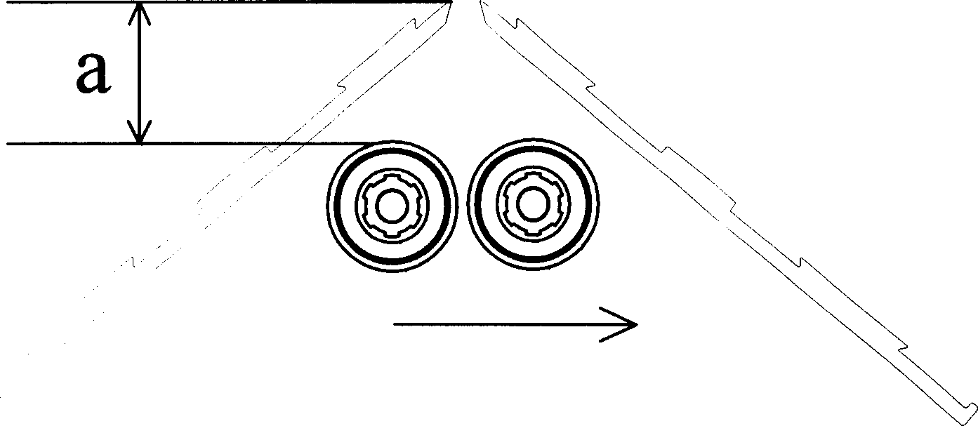
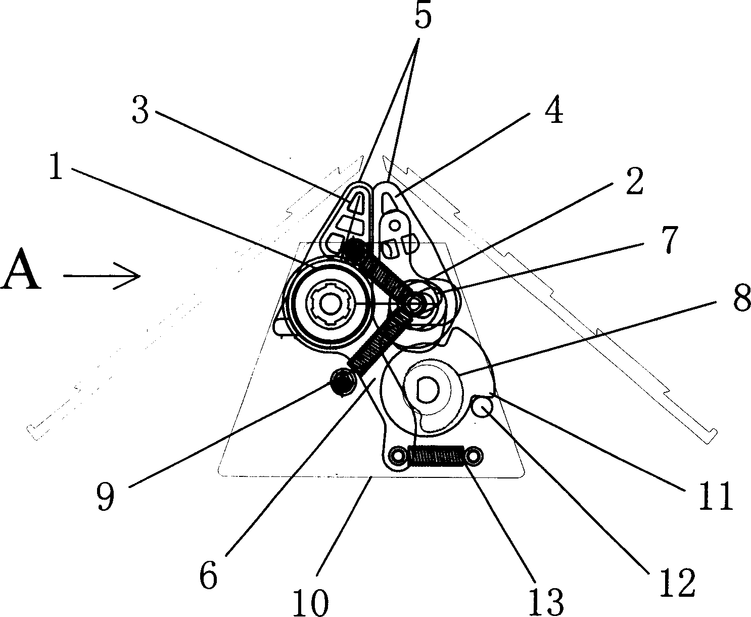
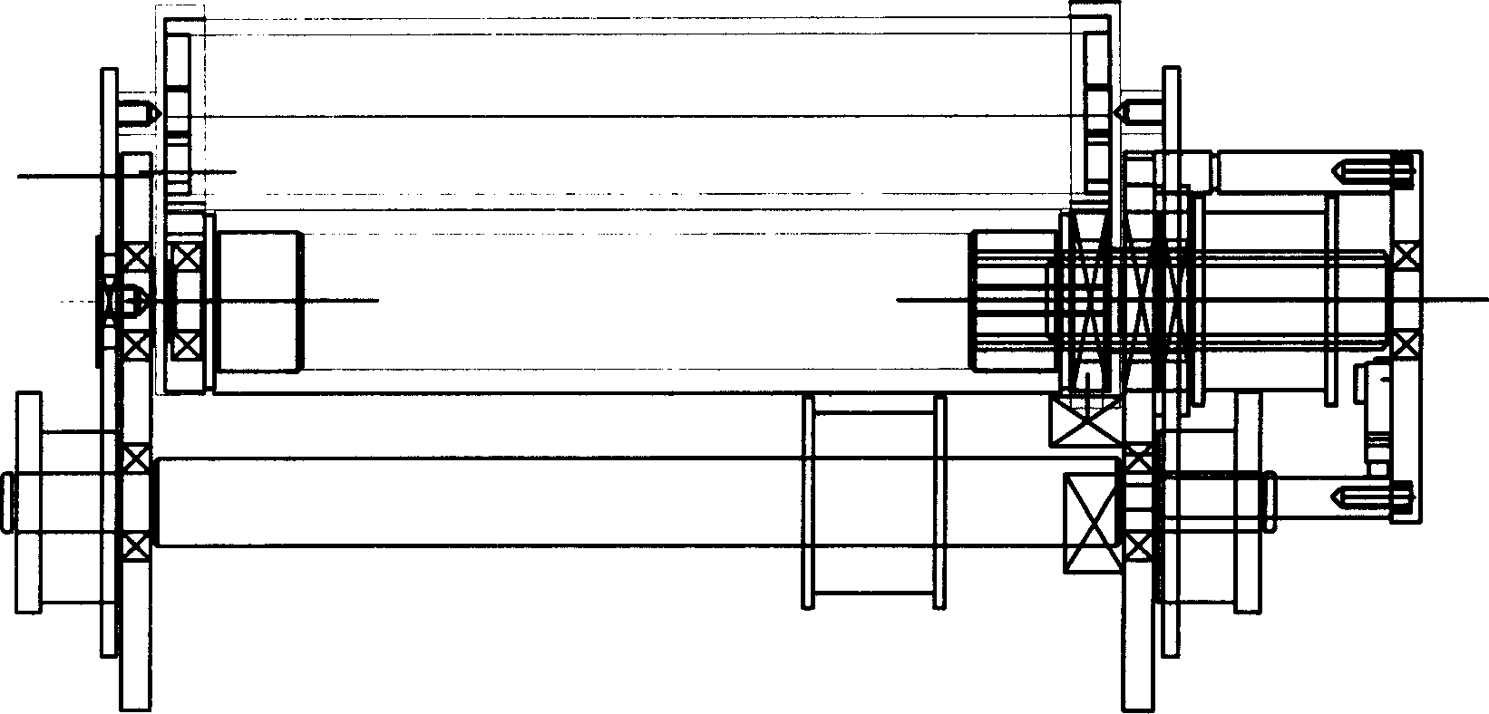
[0017] See Figure 2 to Figure 5 The roller set of the present invention comprises a driving roller 1 with a fixed shaft and a driven roller 2 with a movable shaft, and a driving chuck 3 and a driven chuck 4 are respectively arranged above the two shaft ends of the driving roller 1 and the driven roller 2, The periphery of the driving roller 1 and the driving chuck 3, the driven roller 2 and the driven chuck 4 are respectively covered with a circle of soft material 5, and the soft material 5 is made into a circumferentially sealed type, and then put on the driving roller 1 and the driving chuck 3 , the periphery of the driven roller 2 and the driven chuck 4, so that when the driving roller 1 and the driven roller 2 rotate, it can drive the soft material 5 to circulate, and the soft material 5 moves along the driving chuck 3 and the driven chuck 4 slide downward between the active chuck 3 and the driven chuck 4, if the cloth is placed between the active chuck 3 and the driven c...


PUM


Abstract

The invention provides a roller set. It includes a fixed drive roll and a movable driven roll. They are respectively set on drive and driven collet and covered by round soft material. The two ends of the drive roll shaft are respectively connected with a turnable crank which extends three rocker that the first rocker is connected with driven collet; the second is set a continuous manger in which driven roll shaft can move; the third is set a cam which presses the third at certain position. The shaft end of the driven roll is connected with spring. The distance between the drive and driven rolls and knitting working plate angle is small to save shoulder yarn. Up triangle is open to make multi-needle turn easily. And the drive and driven roll are always adhered to make weaving stable while switching.

Description

technical field [0001] The invention relates to a knitting machine, in particular to a roller group. Background technique [0002] The roller group is a device used in knitting machinery for pulling cloth, guiding yarn, and lifting the bottom. During the bottoming process, the driving roller and the driven roller of the roller group will be opened and closed. The driving roller and the driven roller will be set at the angle formed by the two knitting work plates. The traditional driving roller and driven roller The opening and closing of the moving roller will translate along the linear direction, such as figure 1 As shown in the direction of the arrow, in this way, in order to realize the opening and closing of the driving roller and the driven roller, the distance a between the driving roller and the driven roller and the corner of the knitting work board must be large enough, and the cloth margin when starting the bottom is It will be larger and cause waste. During the...

Claims


Application Information

Patent Timeline
IPC IPC(8): D04B35/02
CPCD04B15/90
Inventor 吴宇芯
Owner 奥华斯精密机械(深圳)有限公司
Why Eureka
Try Eureka