Concrete structure tomographic imaging detection system

A concrete structure and detection system technology, which is applied in the direction of measurement devices, analysis materials, and response signal detection, can solve problems such as limited detection performance, long aftershock tails, and low transmission power, so as to ensure accuracy and consistency, and improve The effect of improving detection efficiency and accuracy

Inactive Publication Date: 2007-02-07
CHANGAN UNIV
View PDF0 Cites 15 Cited by
  • Summary
  • Abstract
  • Description
  • Claims
  • Application Information

AI Technical Summary

Problems solved by technology

[0008] 1) The ultrasonic emission source is made of piezoelectric ceramic materials, and the emission power is small. In the detection of large-volume concrete structures, the signal-to-noise ratio of the received signal is poor, so the detection effect will be seriously degraded;
[0009] 2) The frequency band of the piezoelectric ceramic ultrasonic emission source is narrow, so when the pulse signal is transmitted, the aftershock tail is long (generally more than 5 oscillation cycles), and in the application of thickness measurement, the tail interferes with the reflected wave, which makes the detection severely limited performance
[0010] 3) Using single-channel one-dimensional signal acquisition and analysis, the associated information of adjacent detection points is not effectively utilized

Method used


Image

  • Concrete structure tomographic imaging detection system
  • Concrete structure tomographic imaging detection system
  • Concrete structure tomographic imaging detection system

Examples


Embodiment Construction

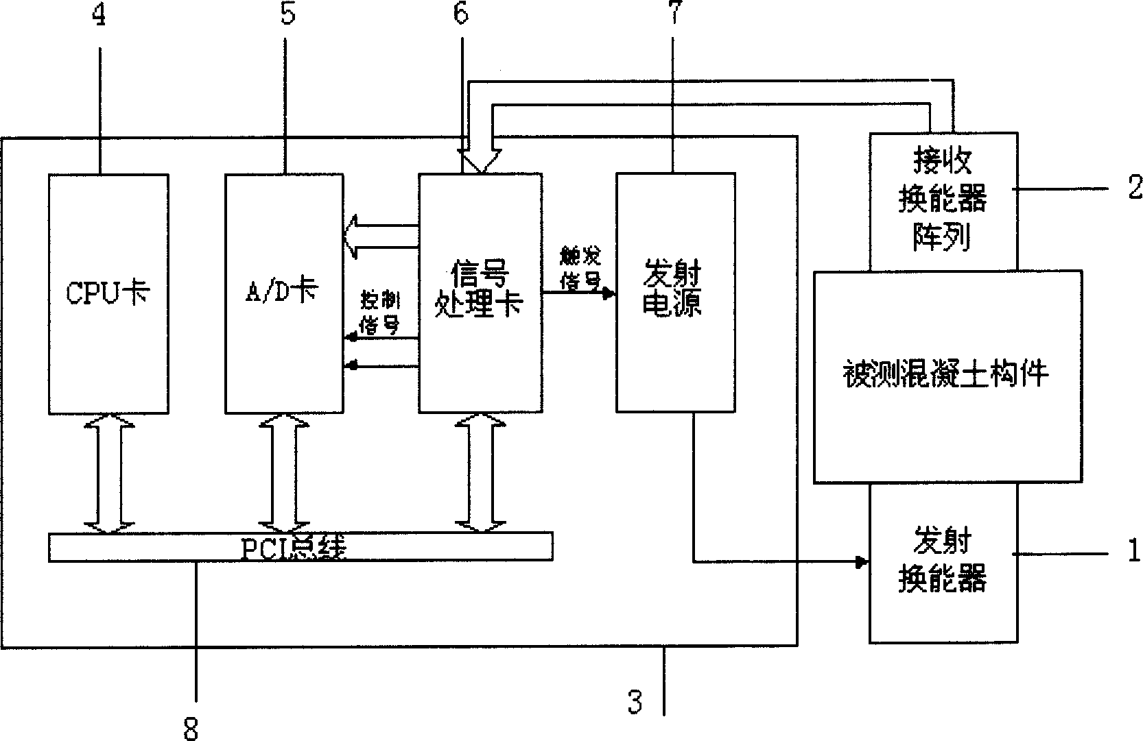
[0022] Refer to figure 1 As shown, the giant magnetostrictive rare earth transmitting transducer 1 is connected to the receiving transducer array 2, the output end of the receiving transducer array 2 is connected to the signal processing card 6, and the signal processing card 6 is connected to the ultrasonic transmitting power source 7. The transmitting power source 7 is connected to the input end of the giant magnetostrictive rare earth transmitting transducer 1, the signal processing card 6 is connected to the AD card 5, and the CPU card 4, the AD card 5, and the signal processing card 6 are connected to the PCI bus 8 respectively.

[0023] The working process of the system is: CPU card 4 sends various configuration commands to signal processing card 6 and A / D card 5 through PCI bus 8, signal processing card 6 and A / D card 5 are ready; after the software executes the start acquisition command, The CPU card 4 writes a start acquisition command to the trigger register of the sign...


PUM


Abstract

The disclosed concrete structure chromatography imaging detection system comprises: a CPU connected by PCI bus, an A / D card, a signal processing card connected with the A / D card and an emission power, and receiving transducer array connected with an ultra-magnetostrictive rare-earth emission transducer. This invention is simple and well precise, and can real-time show the inner structure of concrete accurately.

Description

Technical field [0001] The invention belongs to the concrete structure detection technology, and particularly relates to the concrete structure ultrasonic CT tomography detection technology. Background technique [0002] Concrete structure is one of the important components of bridges, tunnels and industrial and civil buildings, and the detection of its internal characteristics is of great significance for project quality evaluation and safety assessment. The traditional inspection method of concrete structure is to make destructive strength test on cube specimens made by sampling. Practice has shown that the performance indicators of concrete structures measured by the test specimens are often quite different from the actual concrete structures in the structure. Therefore, on-site detection technology that directly detects the performance of concrete structures has become an important means of concrete engineering quality management. [0003] On-site inspection includes two meth...

Claims


Application Information

Patent Timeline
IPC IPC(8): G01N29/06G01N29/36G01N29/24
Inventor 赵祥模宋焕生王国强徐志刚戚秀真沈波杨正华
Owner CHANGAN UNIV
Why Eureka
Try Eureka