Macro inspection apparatus and macro inspection method
A macroscopic inspection and macroscopic technology, applied in the direction of measuring devices, testing of machines/structural components, instruments, etc., can solve problems such as difficulties in implementation
- Summary
- Abstract
- Description
- Claims
- Application Information
AI Technical Summary
Problems solved by technology
Method used
Image

Examples
no. 1 Embodiment approach
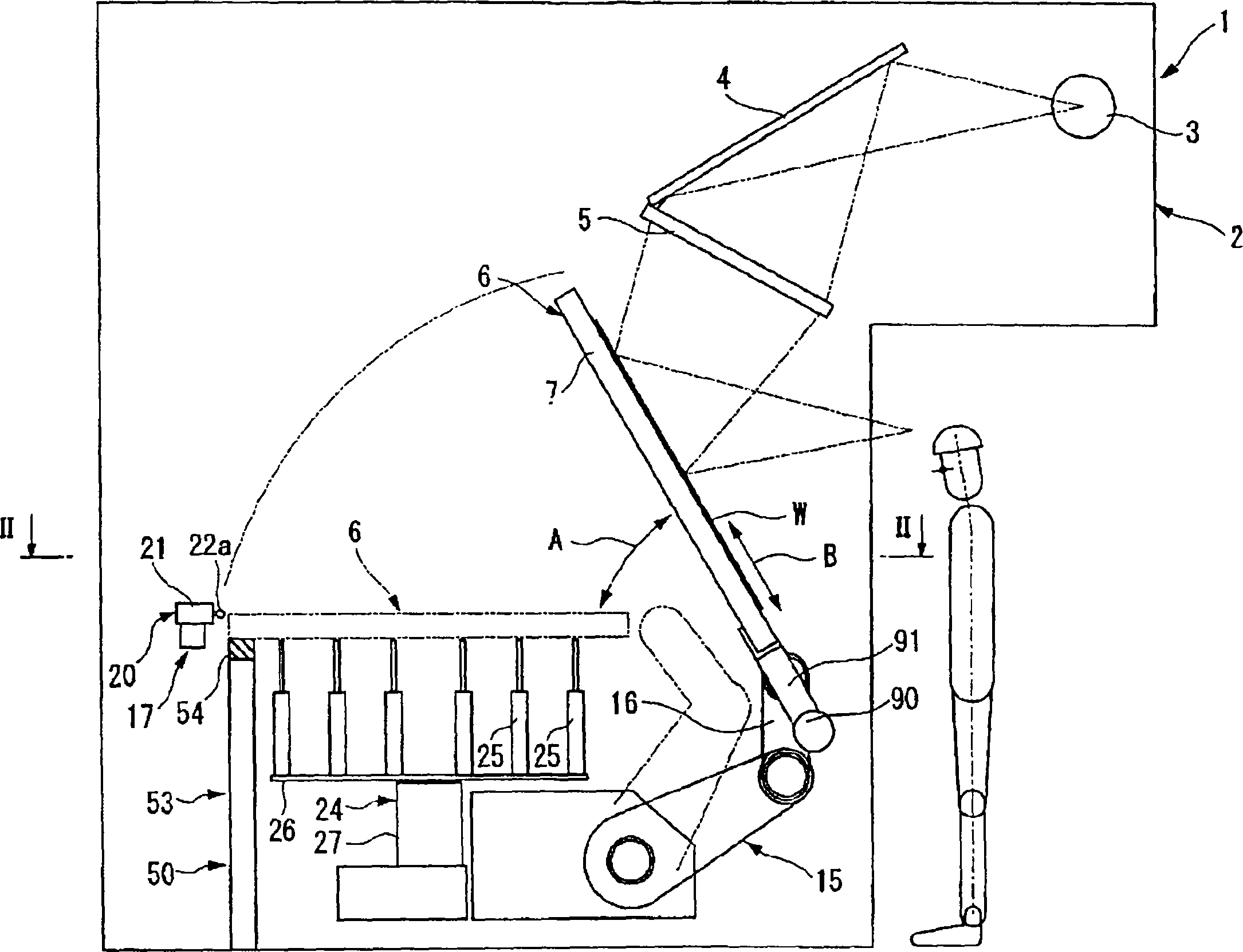
[0090] figure 1 It is a side view showing a schematic configuration of the macroscopic inspection device according to the first embodiment of the present invention.
[0091] The macro-inspection device 1 is arranged in a clean room, and has a device main body 2 having a side wall surrounding a space opened above and below. On the upper surface of the apparatus main body 2 , a filter (not shown) for improving the degree of purification in the apparatus main body 2 is attached. In addition, on the upper part of the device main body 2, as a macroscopic illumination optical system, for example, a light source 3 for macroscopic illumination such as a metal halide lamp or a sodium lamp, and a reflector provided on the optical axis of the illumination light emitted from the light source 3 are provided. 4. Below the reflecting mirror 4, a Fresnel lens 5 is arranged that collects the illumination light from the light source 3 and guides it onto the substrate W. As shown in FIG. The ...
no. 2 Embodiment approach
[0121] Next, a second embodiment of the macroscopic inspection device of the present invention will be described with reference to the drawings. In addition, the same reference numerals are assigned to the same constituent elements as those of the first embodiment described above, and description thereof will be omitted.
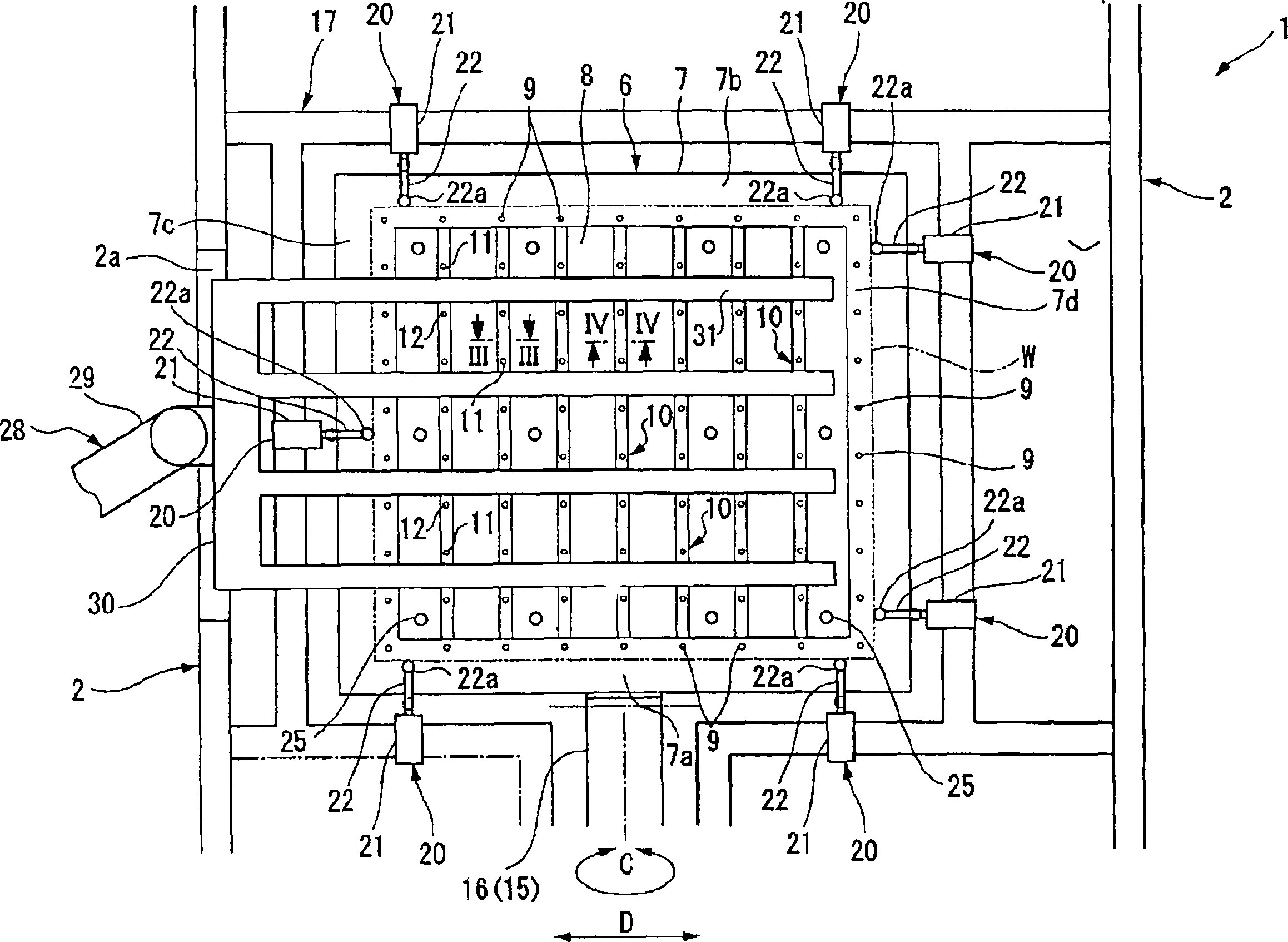
[0122]Such as Figure 6 As shown, on the upper surface of the long side portion 7a of the holder main body 7 of the front end arm 16 of the inspection manipulator 15, two reference pins 42a are fixed as reference positioning units (reference substrate positioning mechanisms). A reference pin 42b is fixed to the upper surface of the side portion 7c. Each reference pin 42a is arranged at a position corresponding to a corner portion of the substrate W, and each reference pin 42b is arranged at a position corresponding to a center portion of the left side of the substrate W. As shown in FIG.
[0123] On the device main body 2, a frame 44 and a frame 45 are ins...
no. 3 Embodiment approach
[0141] Next, a third embodiment of the macroscopic inspection device of the present invention will be described with reference to the drawings. In addition, the same reference numerals are assigned to the same constituent elements as those of the first embodiment described above, and description thereof will be omitted.
[0142] In the present embodiment, a multi-joint arm robot for inspection (the robot for inspection 15 ) is used as a substrate holder drive mechanism for rotating and swinging the substrate holder 6 . Furthermore, in order to make the substrate holder 6 supported freely rotatably and swingably by the inspection manipulator 15, to come to rest quickly at the substrate delivery position, to smoothly perform delivery of the substrate W, to shorten the tact time, and to improve the inspection efficiency, there are Stationary mechanism 50 . Except for the provision of the stationary mechanism 50, it is the same as the above-mentioned first embodiment, and repeate...
PUM
 Abstract
Description
Claims
Application Information
 - R&D
- Intellectual Property
- Life Sciences
- Materials
- Tech Scout
- Unparalleled Data Quality
- Higher Quality Content
- 60% Fewer Hallucinations
Browse by: Latest US Patents, China's latest patents, Technical Efficacy Thesaurus, Application Domain, Technology Topic, Popular Technical Reports.
© 2025 PatSnap. All rights reserved.Legal|Privacy policy|Modern Slavery Act Transparency Statement|Sitemap|About US| Contact US: help@patsnap.com