
Drive train with exhaust gas utilisation and control method

A technology for power transmission and exhaust gas, which is applied in the field of power transmission, can solve the problems of unfavorable weight and high cost, and achieve the effect of improving driving comfort

Inactive Publication Date: 2007-01-17
VOITH TURBO GMBH & CO KG
View PDF0 Cites 6 Cited by
  • Summary
  • Abstract
  • Description
  • Claims
  • Application Information

AI Technical Summary

Problems solved by technology

On the one hand, this design leads to high costs; on the other hand, the additional weight is considered to be a disadvantage especially in motor vehicles, because we know that nowadays people are trying to reduce fuel consumption

Method used


Image

  • Drive train with exhaust gas utilisation and control method
  • Drive train with exhaust gas utilisation and control method
  • Drive train with exhaust gas utilisation and control method

Examples


Embodiment Construction

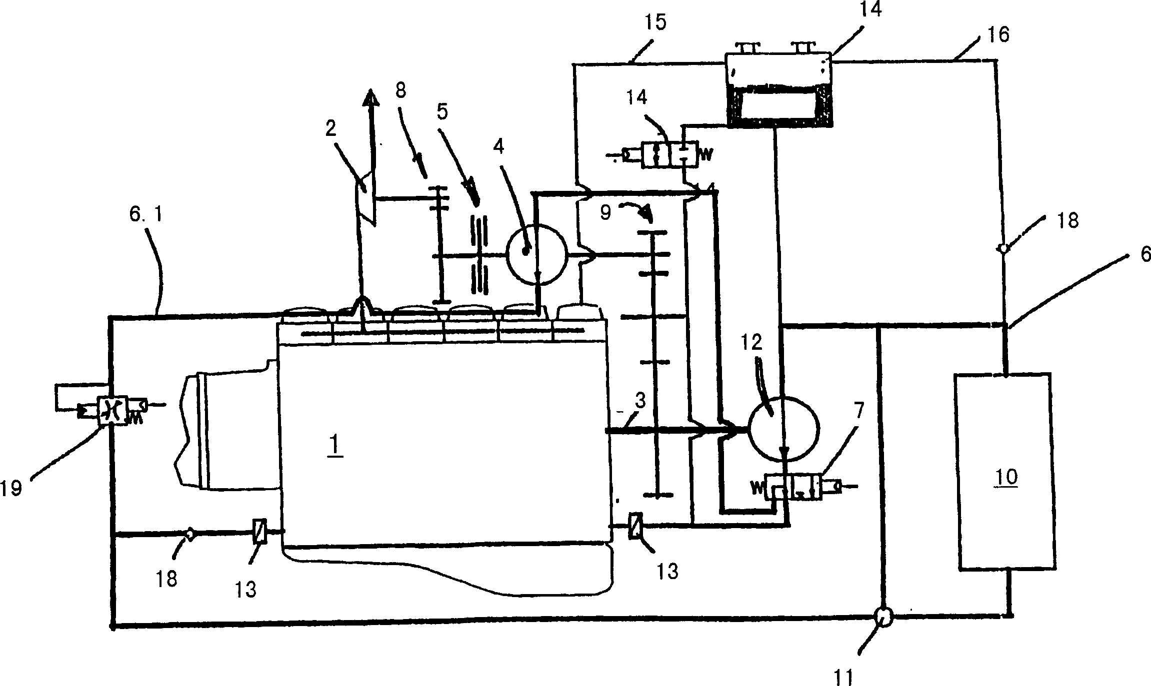
[0022] figure 1 The drive connection between an exhaust gas utilization turbine 2 and a crankshaft 3 of an internal combustion engine, not shown, can be seen in the . The driven shaft of the exhaust gas utilization turbine is connected via a first transmission 8 to the drive wheel 4.1 of the hydrodynamic coupling 4 . The crankshaft 3 is connected to the driven wheel 4 . 2 of the hydrodynamic coupling 4 via a second transmission 9 . Correspondingly, when the working chamber of the hydrodynamic coupling 4 is filled, preferably completely filled, torque or rotational power will be transmitted from the exhaust gas utilization turbine 2 to the crankshaft 3 .

[0023] In order to generate the braking torque, the driving wheel 4 . 1 of the hydrodynamic coupling 4 can be braked and mechanically locked by means of the disc clutch 5 . In the present embodiment, the locking has two effects: firstly the hydrodynamic coupling 4 is used as a retarder, ie the crankshaft 3 then drives the d...


PUM


Abstract

The invention relates to a power train comprising: an internal combustion engine; an exhaust gas utilization turbine arranged in the exhaust gas flow of the internal combustion engine; a crankshaft driven by the internal combustion engine; Connected so that the crankshaft can be driven by the exhaust gas utilization turbine; the hydraulic coupling has a driving wheel and a driven wheel, which form a working chamber with each other, which can be filled with a working medium for torque transmission; the driving wheel and the exhaust gas utilization turbine form a transmission connection; the driven wheel forms a transmission connection with the crankshaft; the relative rotational movement of the driving wheel can be mechanically braked and locked, so that the fluid coupling obtains the function of a hydraulic speed reducer; according to the power transmission system of the present invention The characteristic feature is that a control device is provided, which causes the working chamber of the fluid coupling to be emptied in a targeted manner to a predetermined filling level before and / or while the driving wheel is braked.

Description

technical field [0001] The invention relates to a powertrain, in particular a motor vehicle powertrain, in which the exhaust gas energy of the exhaust gas of an internal combustion engine is used for driving by means of an exhaust gas utilization turbine. Furthermore, the invention relates to a method for controlling such a powertrain. Background technique [0002] In powertrains, especially in motor vehicle powertrains. The use of exhaust gas utilization turbines is well known. According to one known type, during exhaust gas energy utilization, the crankshaft of the internal combustion engine is additionally driven by an exhaust gas utilization turbine, which forms a suitable drive connection with the crankshaft. The drive connection includes a hydrodynamic coupling, which transmits the exhaust gas to the crankshaft using the drive torque of the turbine. A suitable transmission or transmission may also be connected in between. [0003] According to a further development...

Claims


Application Information

Patent Timeline
Patent Type & Authority Applications(China)
IPC IPC(8): F02B41/10
CPCY02T10/163F02B41/10Y02T10/12F02B41/00
Inventor 马库斯·克莱赖因霍尔德·皮蒂乌斯
Owner VOITH TURBO GMBH & CO KG
Learn More