
Stapler

A stapler and staple technology, which is applied in the direction of binding, manufacturing tools, nailing staple tools, etc., can solve the problems of power reduction of the driving device, unreliable starting, difficulty in resetting to its resting position, etc., and achieve low noise Effect

Inactive Publication Date: 2007-01-17
阿科布兰兹美国有限责任公司
View PDF4 Cites 4 Cited by
  • Summary
  • Abstract
  • Description
  • Claims
  • Application Information

AI Technical Summary

Problems solved by technology

Intermittent functional failures of these locking mechanisms, including reduced power to the drive, premature component failure, unreliable actuation, and difficulty resetting to its rest position

Method used


Image

  • Stapler
  • Stapler
  • Stapler

Examples


specific Embodiment approach

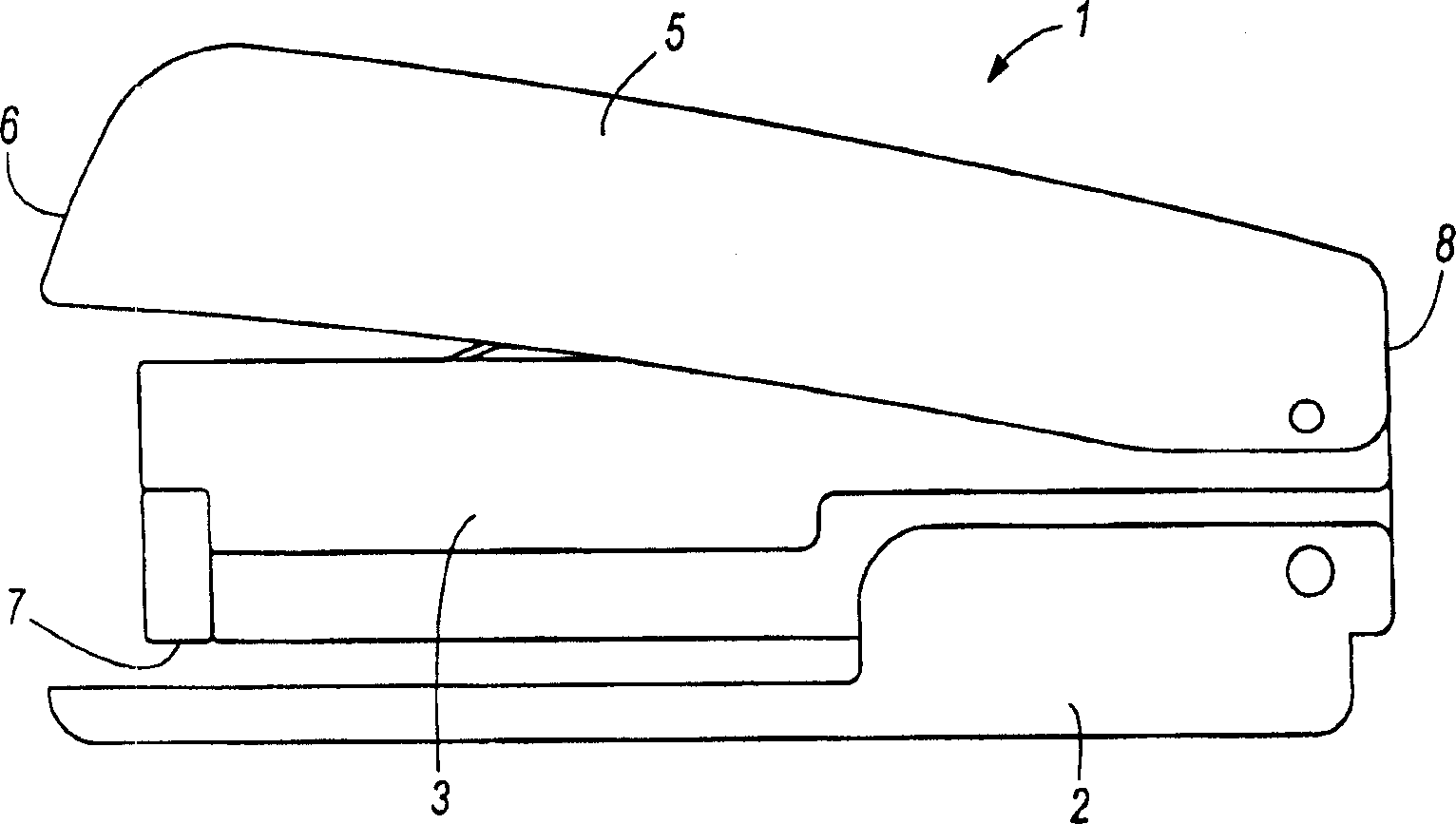
[0061] The first embodiment of the stapler 1 is shown in Figure 1-Figure 11 middle. The appearance of the stapler 1 is as follows figure 1 shown. refer to figure 1 and figure 2 , the stapler 1 defines a front end 6 close to the staple ejection position 7 and a rear end 8 opposite to the front end 6 . The stapler 1 comprises a base 2 , a frame 3 attached to the base 2 and a handle or cover 5 attached to the frame 3 near the rear end 8 of the stapler 1 .

[0062] The base 2 includes an anvil 9 . Those skilled in the art will appreciate that the anvil 9 facilitates clinching or bending of the staples. The base 2 supports the stapler 1 on a support surface such as a desk, a table, a countertop, and the like.

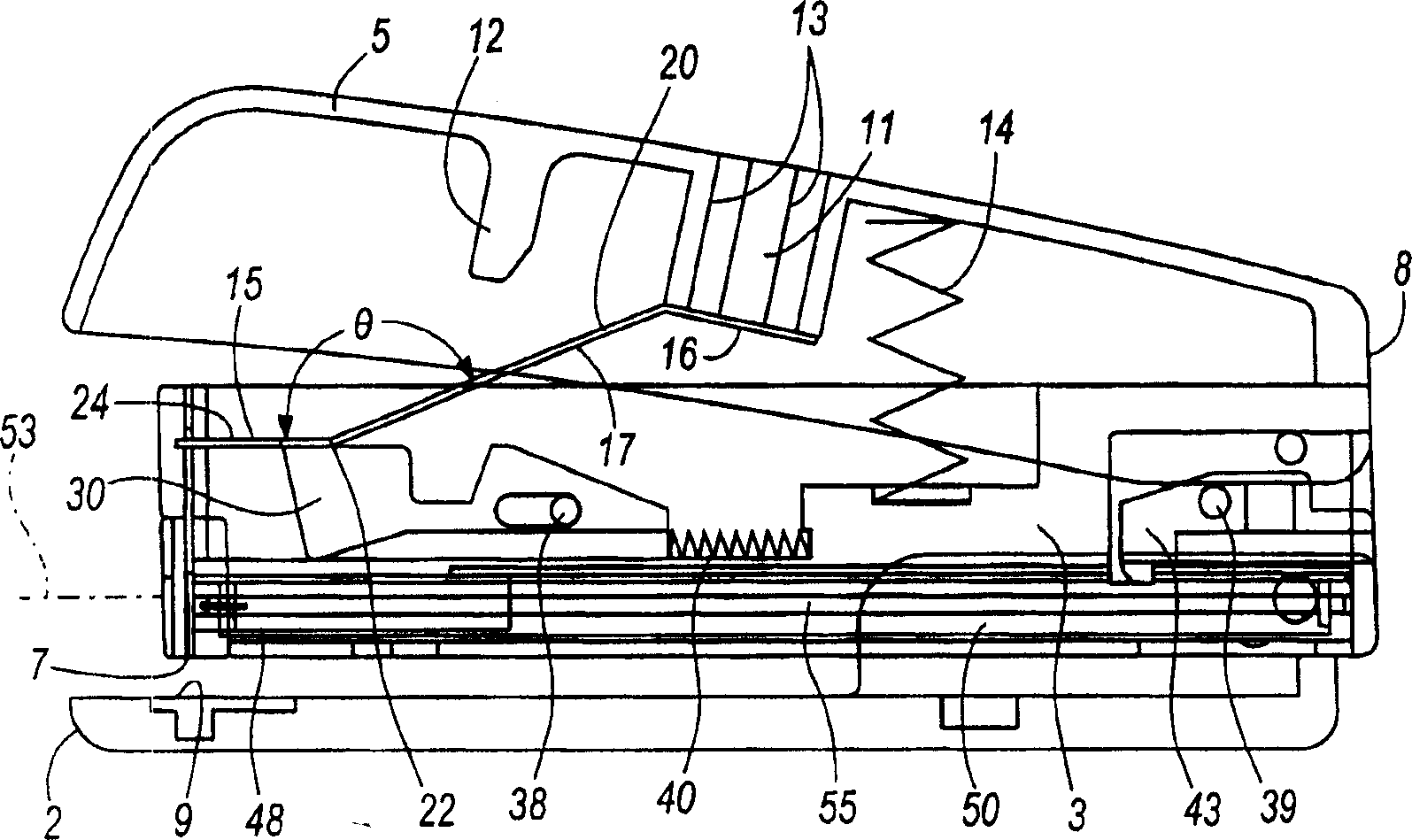
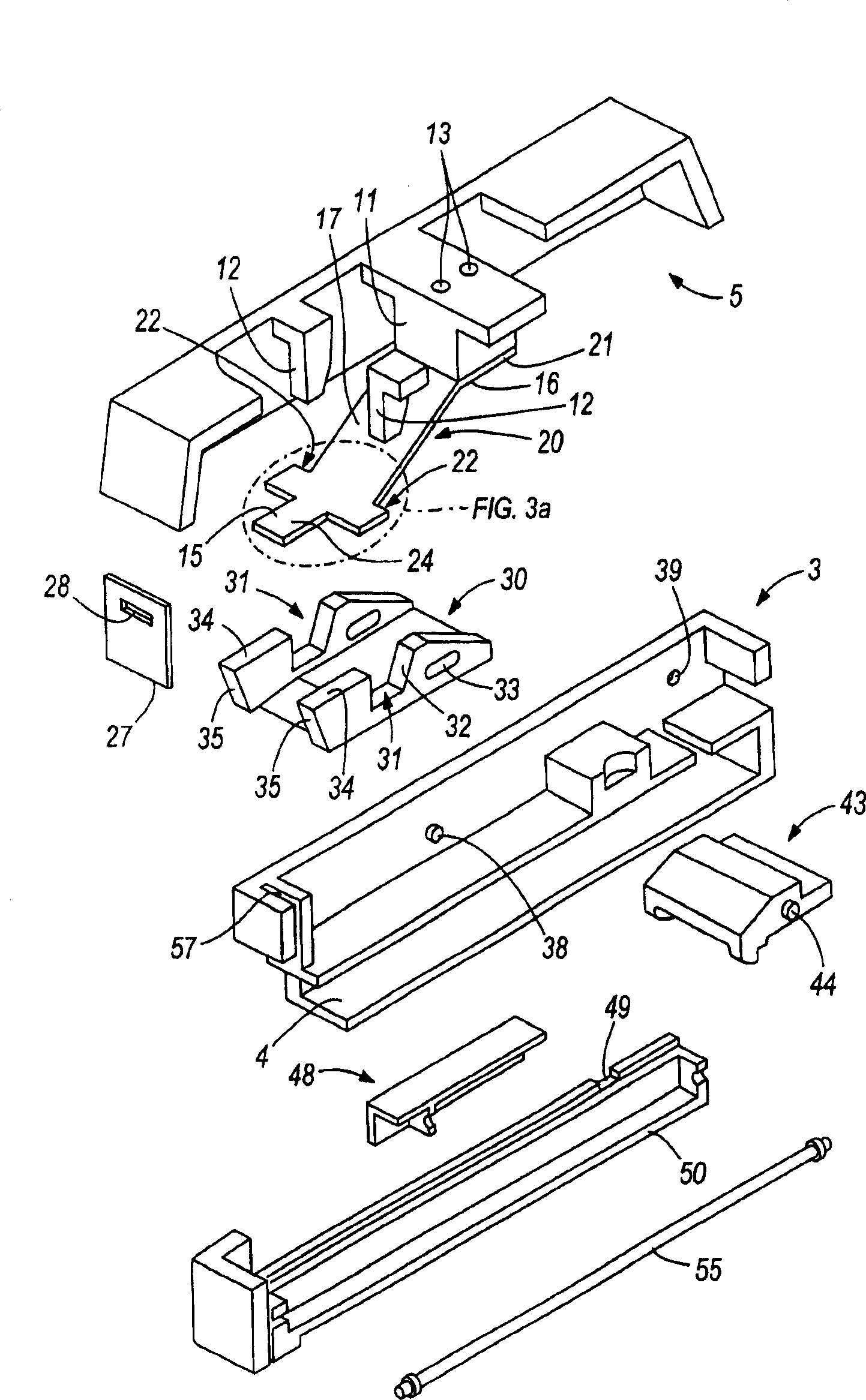
[0063] figure 2 The internal configuration of the stapler 1 is shown when the stapler 1 is not in operation. image 3 is an exploded view showing several components of the stapler 1 . For clarity, image 3 is a cross-sectional view along the longitudinal axis o...


PUM


Abstract

A stapler movable between a rest position and a stapling position and having a front end and a rear end. The stapler includes a base, a staple magazine coupled to the base and configured to hold staples, and a driver blade operable to drive staples out of the staple magazine during stapling operations. The stapler further includes an elastic member coupled to the driver blade and operable to move the driver blade during stapling operations. The elastic member utilizes potential energy to move the driver blade during stapling operations. The driver blade is positioned above the staple magazine when the stapler is in the rest position and the magazine is extendable from the front end of the stapler to allow a user to load staples in the magazine. The stapler is configured such that only the potential energy of the elastic member can operate the driver blade during stapling operations.

Description

[0001] Related Patent Applications [0002] This application claims priority to US Provisional Application 60 / 705,225, filed August 3, 2005, and Japanese Patent Application No. 2005-177441, filed June 17, 2005, the entire contents of which are hereby incorporated by reference. technical field [0003] The present invention relates to staplers, and more particularly to staplers utilizing potential energy to assist in the operation of a staple drive mechanism. There are two types of traditional potential energy or spring assisted office staplers: strong spring type fixed fit or fixed staplers whose spring assist cannot achieve full power without additional user force. Amount of paper required to drive and staple. Background technique [0004] Typically, in a spring-type stapler, the staple is driven into the target object, but the legs of the staple are not bent. The force required to drive the staple is achieved by releasing the pressure built up in the spring or elastic. ...

Claims


Application Information

Patent Timeline
IPC IPC(8): B42B4/00B25C5/02
CPCB25C5/0242
Inventor B·坎达萨米M·哈里斯D·柯比E·T·伊顿D·J·帕佩什B·W·马休斯Y·埃比哈拉Y·哈马古奇
Owner 阿科布兰兹美国有限责任公司
Learn More